
Rotatable engineering machinery rotation constant power control method, system and engineering machinery

A technology of constant power control and construction machinery, applied in the field of rotary constant power control of rotatable construction machinery, rotary constant power control system, and rotary control of rotatable construction machinery, can solve the problems of insufficient precision and pertinence, rough control methods, inability to Targeted control of the rotating speed and other issues of the slewing mechanism to achieve the effect of fine control and good pertinence, ensuring high efficiency and avoiding fluctuations

Active Publication Date: 2012-08-01
ZOOMLION HEAVY IND CO LTD
View PDF6 Cites 4 Cited by
  • Summary
  • Abstract
  • Description
  • Claims
  • Application Information

AI Technical Summary

Problems solved by technology

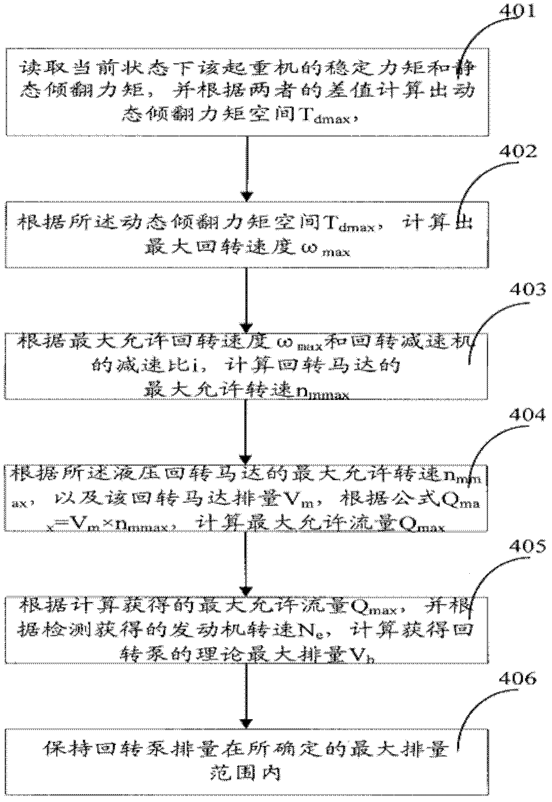
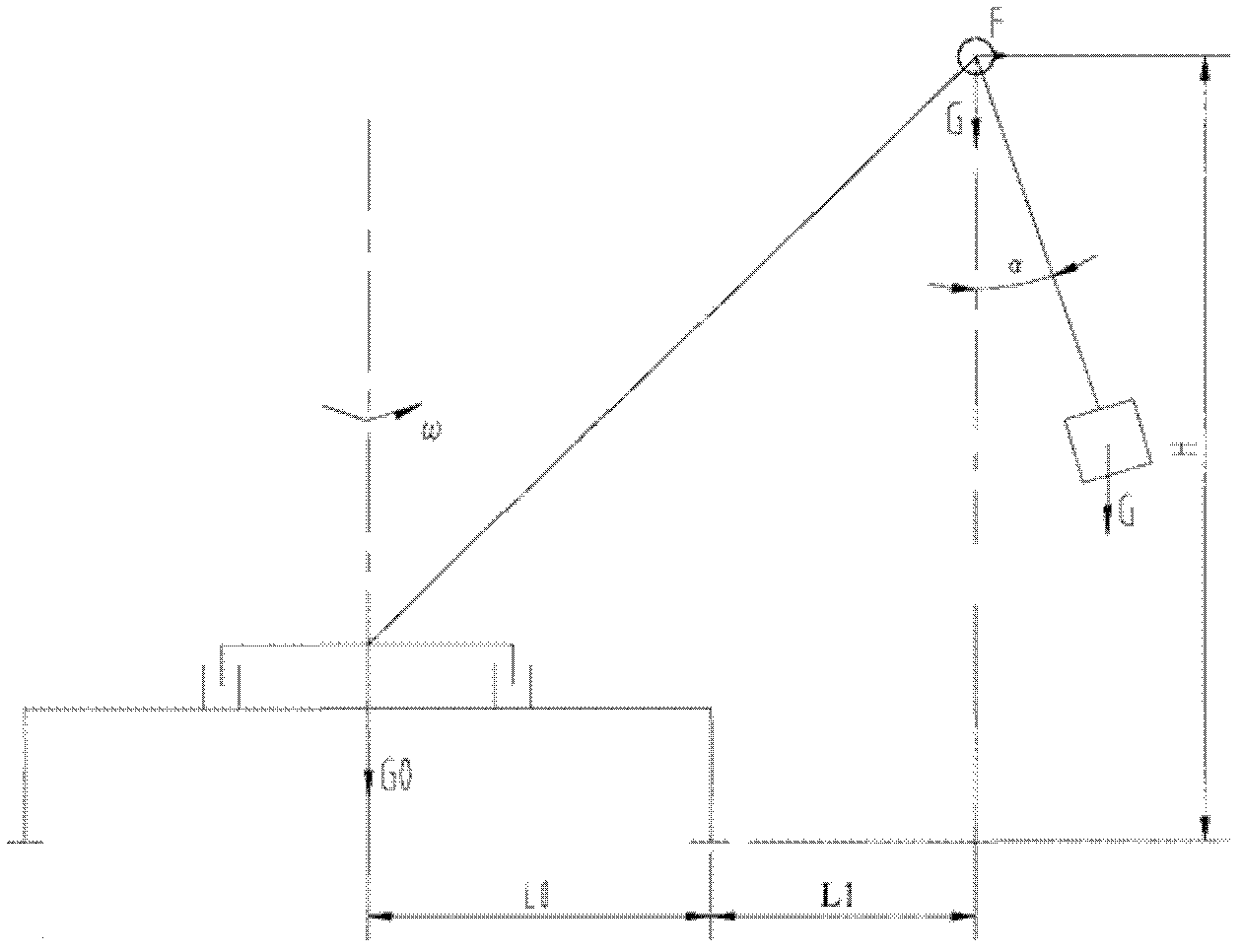
[0005] However, the method for limiting the maximum slewing speed of the above-mentioned patent application uses the stabilizing moment and the static overturning moment as the reference value to propose a method for limiting the maximum slewing speed of the slewing mechanism from the safety angle of "overturning" and the static point of view, and does not involve the slewing process The difference in the maximum rotary speed between heavy objects of different weights under the same working range and the difference in the maximum rotary speed between heavy objects of the same weight under different working ranges, in fact, the above-mentioned control method in the prior art still belongs to one This is a relatively rough control method, which cannot control the speed of the slewing mechanism in a targeted manner according to the weight of the lifting weight and the difference in the working range, so the fineness and pertinence of the control are not enough

Method used


Image

  • Rotatable engineering machinery rotation constant power control method, system and engineering machinery
  • Rotatable engineering machinery rotation constant power control method, system and engineering machinery
  • Rotatable engineering machinery rotation constant power control method, system and engineering machinery

Examples


Embodiment Construction

[0037] The specific embodiments of the present invention will be described in detail below in conjunction with the accompanying drawings. It should be understood that the specific embodiments described here are only used to illustrate and explain the present invention, and the protection scope of the present invention is not limited to the following specific embodiments. .

[0038] First of all, it should be noted that although the crane is mainly used as an example in the following description, it is obvious to those skilled in the art that the slewing constant power control method and its control system of the present invention can be widely applied to various cranes that need to be lifted. Heavy rotatable construction machinery, such as single-bucket excavators, etc. In addition, in the following description, some well-known technical contents will be appropriately briefly described.

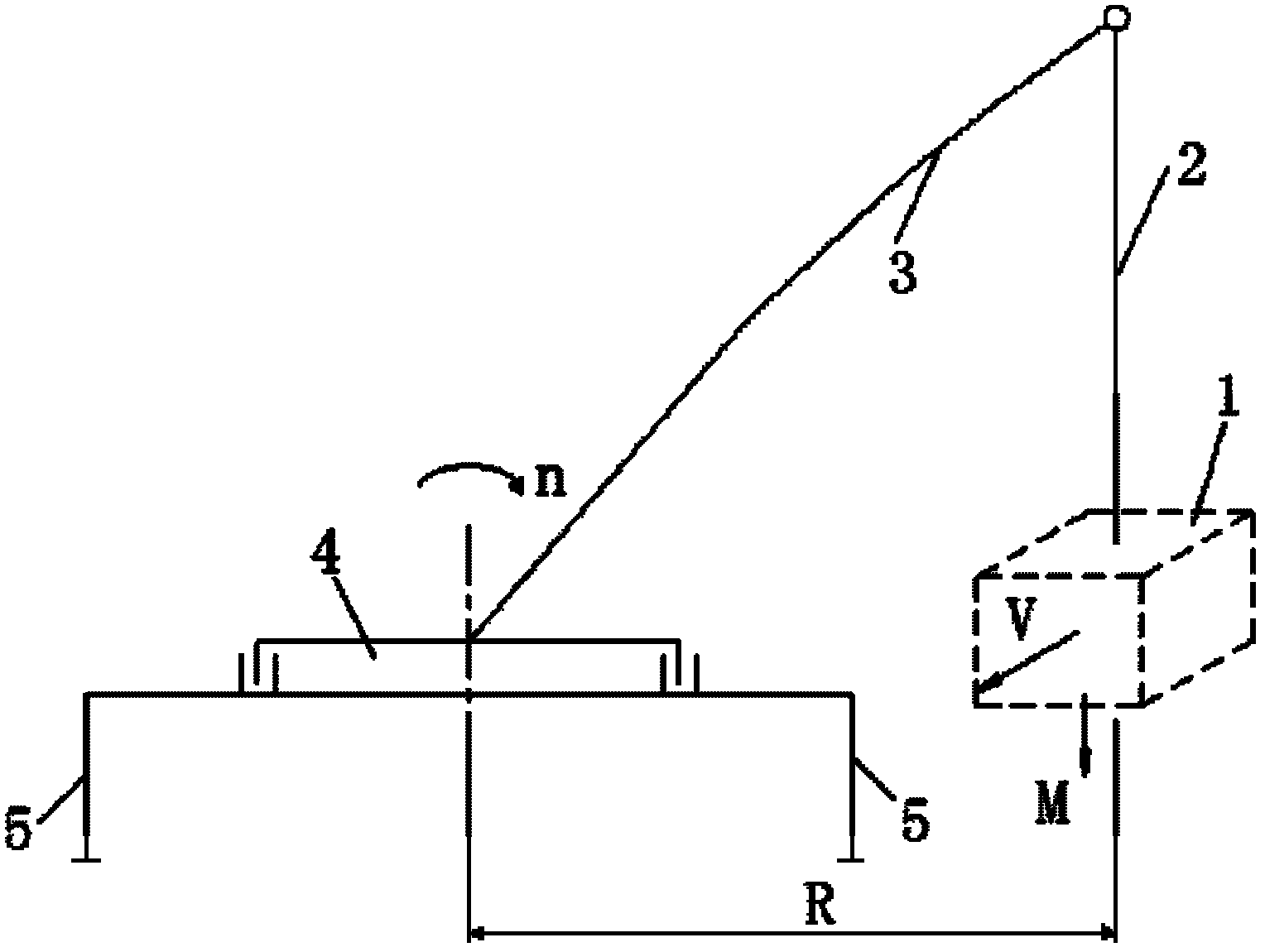
[0039] see image 3 As shown, when a rotatable engineering machine, such as a truck cra...


PUM


Abstract

A rotatable engineering machinery rotation constant power control method comprises step one (101) of calculating rotation reference power P=MxgxV, wherein the M is mass of lifted heavy objects, the g is a constant of the gravitational acceleration, and the V is rotation linear velocity of the heavy objects; step two (201) of calculating rotate velocity of a rotation platform n=Px9.549 / rated T, wherein the rated T is the rated output torque of a reduction box connected with a rotation driving device; and step three (301) of controlling actual rotation velocity of the rotation platform to be equal to the rotate velocity n of the rotation platform. In addition, the invention further provides a rotation constant power control system and rotatable engineering machinery used for achieving the control method. The control method and the control system can achieve control objectives of rotation operation velocity of the heavy objects of being fast in light or close objects and being slow in heavy or far objects according to different weight and working radius, and guarantee high efficiency of rotation operation and maximum utilization of structural strength of the whole machine.

Description

technical field [0001] The invention relates to a method for controlling the rotation of a rotatable construction machine, in particular to a method for controlling the rotation of a rotatable construction machine with constant power. On this basis, the present invention relates to a slewing constant power control system for realizing the slewing constant power control method. In addition, the present invention also relates to a rotatable engineering machine comprising the rotatable constant power control system. Background technique [0002] Rotary construction machinery is widely used in the field of construction machinery. It is mainly divided into two parts: loading and unloading. The loading part mainly includes the rotary mechanism and the operating mechanism installed on the rotary table of the rotary mechanism. A typical example is a truck crane. During the working process of the truck crane, in order to expand the scope of work and enhance the flexibility of the jo...

Claims


Application Information

Patent Timeline
IPC IPC(8): B66C23/94
CPCB66C23/94B66C13/20
Inventor 詹纯新刘权张建军李义李英智
Owner ZOOMLION HEAVY IND CO LTD
Learn More