Transmission assembly of agitator type washing machine

The invention relates to a washing machine and agitating technology, which is applied to the transmission assembly field of agitating washing machines, and can solve the problems of uncoordinated coordination between brakes and drives, shortened service life of the drive motor, inconvenient installation and maintenance, etc., and achieves simple structure, accurate braking, and occupancy. small space effect

Inactive Publication Date: 2012-08-01
CHANGZHOU XINYA ELECTROMOTOR
View PDF4 Cites 9 Cited by
  • Summary
  • Abstract
  • Description
  • Claims
  • Application Information

AI Technical Summary

Problems solved by technology

When washing, the positive and negative rotation of the pulsator can better wash the clothes and prevent the clothes from being entangled. The positive and negative rotation of the pulsator is generally realized by the controller controlling the positive and negative rotation of the drive motor. This transmission mode is due to the Frequent starting and forward and reverse rotation greatly shorten the service life of the drive motor
[0003] In addition, due to the working requirements of the washing machine, the transmission mechanism must complete the deceleration operation of the pulsator under the washing condition, and at the same time, the inner tub must remain stationary, while under the dehydration condition, the pulsator and the inner tub must rotate at high speed synchronously. Brake in time when necessary, so the structure is relatively complicated and requires the effective cooperation of the clutch mechanism and the brake mechanism. In the prior art, the clutch mechanism is generally composed of a ratchet, a pawl, and a lever for controlling the clutch of the pawl, and an additional The brake mechanism is relatively large in size and complicated in structure, and it is inconvenient to install and maintain. At the same time, because the brake mechanism is set up separately, it is easy to cause the problem of incoordination between brake and drive, and sometimes the brake and drive are performed simultaneously or the drive stops. The situation of braking after a period of time is not conducive to use

Method used


Image

  • Transmission assembly of agitator type washing machine
  • Transmission assembly of agitator type washing machine
  • Transmission assembly of agitator type washing machine

Examples


Embodiment Construction

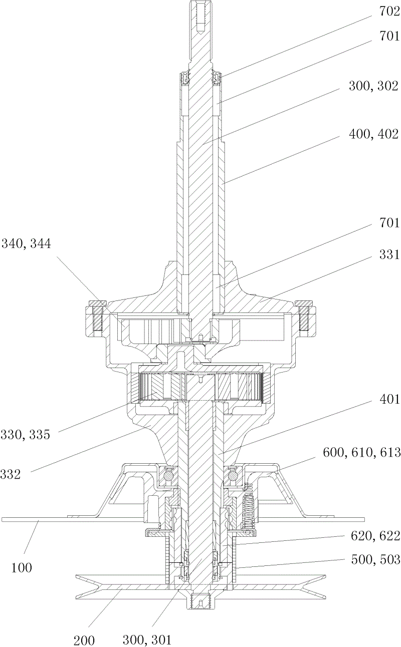
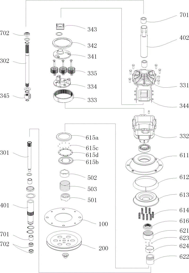
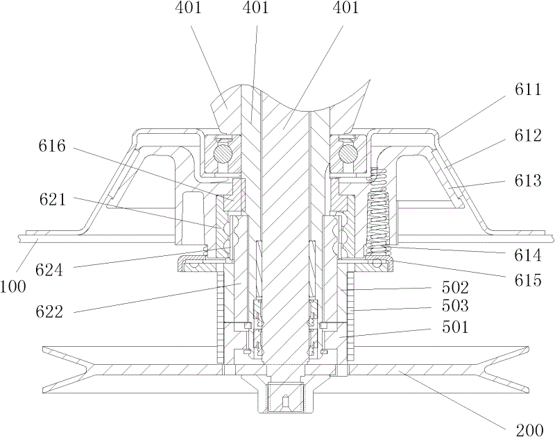
[0037] See Figure 1 to Figure 3 , the present invention has a mounting plate 100 connected with the washing machine shell, a driving pulley 200, a spindle assembly 300 fixedly connected with the washing machine pulsator, a bushing 400 fixedly connected with the washing machine inner tub, a clutch device 500 and a braking device 600, the spindle assembly The lower end of 300 is fixedly connected with the drive pulley 200, the shaft sleeve 400 is coaxially arranged to rotate with the main shaft assembly 300, and the lower part of the shaft sleeve 400 is connected with the drive pulley 200 through the clutch device 500; the main shaft assembly 300 has an input shaft 301 and an output shaft 302, and the input shaft Between the shaft 301 and the output shaft 302, a planetary gear reduction assembly 330 and a forward and reverse output assembly 340 are arranged. The brake device 600 has a cone-disc brake mechanism 610 and a brake control mechanism 620; The connected frustum flange ...


PUM


Abstract

The invention relates to a transmission assembly of an agitator type washing machine. The transmission assembly comprises a mounting plate connected with a shell of the washing machine, a driving belt pulley, a main shaft component which is fixedly connected with an impeller of the washing machine, a shaft sleeve which is fixedly connected with an inner barrel of the washing machine, a clutching device and a braking device, wherein the lower end of the main shaft component is fixedly connected with the driving belt pulley; the shaft sleeve and the main shaft component are coaxially arranged in a rotating mode; the lower part of the shaft sleeve is connected with the driving belt pulley through the clutching device; the main shaft component consists of an input shaft and an output shaft; a planet wheel speed reduction component and a positive and negative rotation output component are arranged between the input shaft and the output shaft; and the braking device is provided with a conical disc braking mechanism and a braking control mechanism. According to the transmission assembly, a square thread clutching device, a frustum-shaped braking device, a planet wheel speed reduction device, a rack and a sector gear are used for outputting positive and negative torque; and the transmission assembly has a simple structure and long service life, is reliably driven and accurately braked, occupies a small space, is convenient to mount and maintain and is high in novelty and creativity.

Description

technical field [0001] The invention relates to a transmission mechanism of a washing machine, in particular to a transmission assembly of a stirring type washing machine. Background technique [0002] Similar to other washing machines, agitating washing machines have washing and dehydration conditions. Under washing conditions, the pulsator rotates forward and reverse to achieve the purpose of washing; under dehydration conditions, the pulsator rotates synchronously with the inner tub at high speed to achieve the purpose of dehydration. When washing, the forward and reverse rotation of the pulsator can better wash the clothes and prevent the clothes from being entangled, and the forward and reverse rotation of the pulsator is generally realized by the controller controlling the forward and reverse rotation of the driving motor. Frequent starting and forward and reverse rotation shorten the service life of the drive motor. [0003] In addition, due to the working requiremen...

Claims


Application Information

Patent Timeline
Patent Type & Authority Applications(China)
IPC IPC(8): D06F37/40D06F37/30
CPCD06F37/40D06F13/02D06F37/30
Inventor 陈昌
Owner CHANGZHOU XINYA ELECTROMOTOR
Why Eureka
Try Eureka