Chlorine bypass system and method for treating extracted gas from chlorine bypass

A bypass system and treatment method technology, applied in waste heat treatment, lighting and heating equipment, furnace components, etc., can solve problems such as increased heat loss, coating failure, and reduced slag production in cement sintering systems

Inactive Publication Date: 2012-08-01
TAIHEIYO CEMENT CORP
View PDF13 Cites 2 Cited by
  • Summary
  • Abstract
  • Description
  • Claims
  • Application Information

AI Technical Summary

Problems solved by technology

[0004] In the above-mentioned chlorine bypass system 31, since there is a large amount of SO in the exhaust gas G3 of the bag filter 38 2 Therefore, the exhaust gas G3 cannot be released directly to the outside of the system, and the exhaust gas G3 is returned to the side of the fan (IDF) that guides the exhaust gas of the cement kiln 32 through the exhaust fan 40
At this time, if the exhaust gas G3 is returned to the preheater attached to the cement kiln 32, there will be the following problems: the heat loss of the cement sintering system will increase, the slag production will decrease, and the concentration zone due to sulfur will be caused. Incoming coating failure
[0005] On the other hand, a method of utilizing the above-mentioned exhaust gas G3 as air for fuel combustion of the cement raw material sintering system has been proposed. However, in this method, as in the above, the sulfur content is concentrated in the sintering process, so there are problems caused by the concentration of sulfur content. Problems such as coating failure and the like (refer to Patent Document 2)

Method used


Image

  • Chlorine bypass system and method for treating extracted gas from chlorine bypass
  • Chlorine bypass system and method for treating extracted gas from chlorine bypass
  • Chlorine bypass system and method for treating extracted gas from chlorine bypass

Examples


Embodiment Construction

[0048] Next, modes for implementing the present invention will be described with reference to the drawings in the specification.

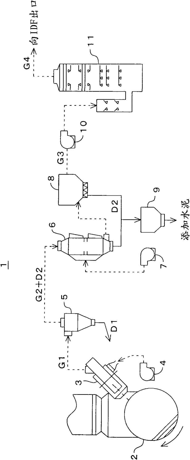
[0049] figure 1 Showing one embodiment of the chlorine bypass system of the present invention, the chlorine bypass system 1 is characterized in that it includes a kiln exhaust flow path from the kiln tail of the cement kiln 2 to the lowest stage cyclone (not shown). A sampler 3 that extracts part of the combustion gas, a cooling fan 4 that supplies cold air into the sampler 3 to quench the extraction gas G1, and a cyclone that serves as a classifier for separating the coarse powder D1 of dust contained in the extraction gas G1 5. Cool the cooler 6 of the exhaust gas G2 containing the fine powder D2 discharged from the cyclone 5, the cooling fan 7 supplying cold wind to the cooler 6, and the fine powder D2 in the exhaust gas G2 cooled by the cooler 6. The bag dust collector 8 for dust collection, the dust tank 9 for recovering the fine powder D2 d...


PUM


Abstract

The invention provides a chlorine bypass system and a method for treating extracted gas from a chlorine bypass and is used for fulfilling the aims of reducing cost, avoiding increase of heat loss of a cement sintering system and decrease of slag yield, suppressing concentration of a sulfur component, an organic component and a chlorine component and exhausting of the sulfur component, the organic component and the chlorine component from a chimney to the outside of the system, and treating exhausted gas from the chlorine bypass. The chlorine bypass system (1) comprises a sampler (3), a dried dust collector (8) and a device (11), wherein the sampler (3) is used for extracting a part of combustion gas from a kiln gas exhaust flow passage between the tail of a cement kiln (2) and a lowermost cyclone; the dried dust collector (8) is used for collecting dust (D2) contained in the extracted gas (G1) which is extracted by using the sampler; and the device (11) is used for removing and recovering harmful components contained in exhausted gas (G3) which is subjected to dust collection. By supplying the purified extracted gas, namely exhausted gas (G4), to an outlet of a guide fan which is arranged at the outlet of a pre-heater attached to the cement kiln, chlorine bypass rate can be improved.

Description

technical field [0001] The present invention relates to a chlorine bypass (Japanese: 塩素バイパス) system for removing chlorine by extracting a part of the combustion gas from the kiln exhaust flow path from the kiln tail of the cement kiln to the lowest stage cyclone (Japanese: サィクロン) of the preheater , and methods of dealing with its exhaust. Background technique [0002] At present, focusing on chlorine, sulfur, alkali, etc., which cause problems such as clogging of the preheater of cement manufacturing equipment, chlorine is particularly a problem, and the kiln discharge from the kiln tail of the cement kiln to the lowest stage cyclone is used. A chlorine bypass system that withdraws a portion of the combustion gases from the gas flow path to remove chlorine. [0003] As such a chlorine bypass system such as figure 2 As shown, a chlorine bypass system 31 is proposed, which is equipped with a sampler ( Japanese: プロロブ) 33, a cooling fan 34 for quenching the extraction gas G1 ...

Claims


Application Information

Patent Timeline
Patent Type & Authority Applications(China)
IPC IPC(8): F27D17/00C04B7/36
CPCC04B7/43F27D17/001
Inventor 寺崎淳一斋藤绅一郎小竹将宫崎武史山本泰史
Owner TAIHEIYO CEMENT CORP
Why Eureka
Try Eureka