Ferroalloy mine heat furnace system with waste heat power generation system

A waste heat power generation and submerged arc furnace technology, applied in furnaces, waste heat treatment, furnace components, etc., can solve the problems of waste heat resources, thermal pollution of workers' production environment, etc., and achieve the effect of saving secondary energy and reducing thermal pollution.

Inactive Publication Date: 2012-08-01
BEIJING CENTURY BENEFITS
View PDF5 Cites 12 Cited by
  • Summary
  • Abstract
  • Description
  • Claims
  • Application Information

AI Technical Summary

Problems solved by technology

The processing method of high-temperature flue gas in the prior art causes a large amount of valuable flue gas heat to be lost to the atmosphere in the steel bare pipe flue 6 and the surface cooler 18, which not only wastes valuable waste heat resources, but also causes workers to produce thermal pollution of the environment

Method used


Image

  • Ferroalloy mine heat furnace system with waste heat power generation system
  • Ferroalloy mine heat furnace system with waste heat power generation system
  • Ferroalloy mine heat furnace system with waste heat power generation system

Examples


Embodiment 1

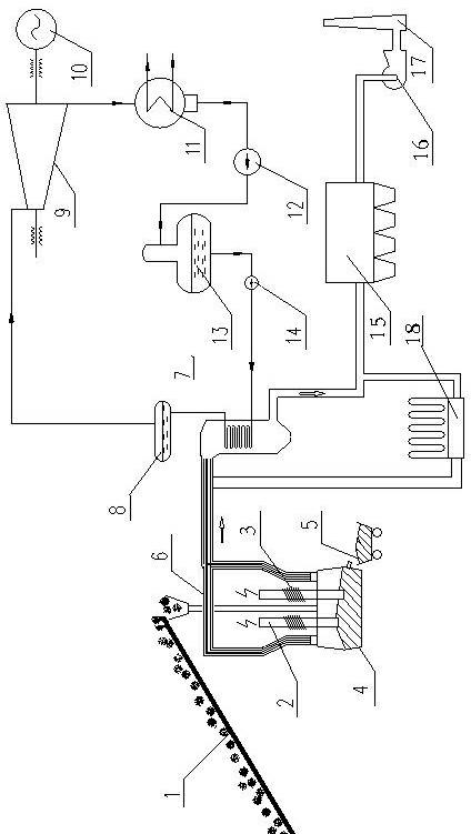
[0018] like figure 2 As shown, the ferroalloy submerged arc furnace system with waste heat power generation system in this embodiment includes: feeding system 1, electrode holding, pressing and lifting system 2, electrode water cooling system 3, submerged arc furnace body 4, and tapping system 5 , waste heat power generation system and dust removal system, etc. The waste heat power generation system includes: high temperature flue 6, waste heat boiler 7, power generation system and water treatment system, etc. The power generation system includes a steam turbine 9 and a generator 10 , the water treatment system includes a condenser 11 , a condensed water pump 12 , a deaerator 13 and a feed water pump 14 ; the dust removal system includes a dust removal fan 16 and a discharge chimney 17 . The high-temperature flue 6 can adopt an inner heat-insulation flue in the form of inner heat preservation, a heat-resistant stainless steel flue or a vaporization cooling flue that adopts a...

Embodiment 2

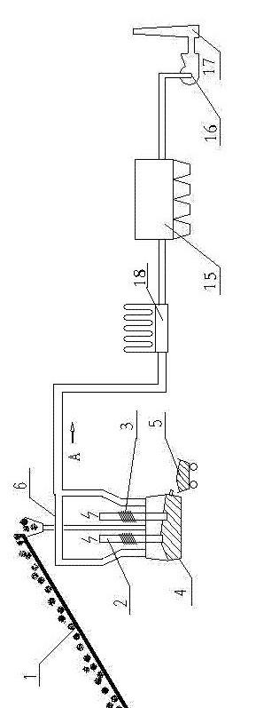
[0021] like image 3 As shown, the composition and structural form of the ferroalloy submerged arc furnace system in this embodiment are basically the same as in embodiment 1, the difference is that a surface cooler 18 is also arranged in the ferroalloy submerged arc furnace system in this embodiment, the The surface cooler 18 is arranged in parallel with the waste heat power generation system as a bypass of the waste heat power generation system between the high temperature flue gas pipeline 6 and the dust removal system. This system retains the surface cooler 18 in the flue gas dedusting system of the submerged arc furnace originally designed, so that the waste heat boiler 7 acts as a parallel bypass of the surface cooler 18, and when the waste heat boiler 7 is running, the surface cooler is closed by operating the flue valve 18 this branch and open the waste heat boiler 7 this branch, the heat of the high-temperature flue gas of the submerged arc furnace is replaced from th...


PUM


Abstract

A ferroalloy mine heat furnace system with a waste heat power generation system comprises a motor control system, an electrode slipping device, an electrode positioning system, a charging system, iron tapping equipment, a protection facility, an electrode water cooling system, a waste heat recovery power generation system and a dust collecting system, wherein the waste heat recovery power generation system recovers the high-temperature flue gas generated during the production process of the ferroalloy mine heat furnace system, generates steam through a waste heat boiler and drives a supporting steam turbine generator set to generate electricity. Through additional arrangement of waste heat recovery power generation system, the ferroalloy mine heat furnace system provided by the invention not only recovers flue gas and avoids secondary energy waste, but also reduces the thermal pollution of high-temperature flue gas to the working environment of workers, and is the novel ferroalloy mine heat furnace system which meets the development mode of circular economy.

Description

technical field [0001] The invention relates to a ferroalloy submerged arc furnace system with waste heat power generation system. Background technique [0002] The production methods of ferroalloys are classified into blast furnace method, submerged arc furnace method, out-of-furnace method, vacuum resistance furnace method and oxygen converter method according to the equipment used. Among them, the submerged arc furnace method is the main method of ferroalloy production, and about 72% of the ferroalloy output is produced by this method. The submerged arc furnace method is to use charcoal as a reducing agent to produce ferroalloys, and the electric furnace used is usually an ore reduction furnace (submerged arc furnace for short). The source of heat in the smelting process is electric energy, and charcoal is used as a reducing agent. [0003] The mechanical equipment of ferroalloy submerged arc furnace is relatively complicated. In addition to the submerged arc furnace bo...

Claims


Application Information

Patent Timeline
Patent Type & Authority Applications(China)
IPC IPC(8): F27D17/00
CPCY02P10/25Y02P80/15
Inventor 陈恩鉴高德云程珩涂爱民
Owner BEIJING CENTURY BENEFITS
Why Eureka
Try Eureka