Resonance excitation method of micro-cantilever sensor

A technology of micro-cantilever beam and resonance excitation, which is applied in the direction of using electric/magnetic devices to transmit sensing components, can solve the problems of unable to achieve probe resonance excitation, unable to reach resonance frequency, unable to perform dynamic detection, etc., and achieve easy and precise control. , The effect of easy production and processing, high-speed real-time detection

Inactive Publication Date: 2014-04-30
SHANDONG UNIV
View PDF6 Cites 0 Cited by
  • Summary
  • Abstract
  • Description
  • Claims
  • Application Information

AI Technical Summary

Problems solved by technology

Their advantage is that they have a higher quality factor, and a high quality factor is of great significance for improving detection accuracy; the disadvantage is that it is difficult to achieve resonance excitation
Commonly used signal generators can only generate electrical signals with a frequency of tens of MHz. For micro-cantilever beams with high resonant frequencies, their resonant frequency cannot be reached.
Usually, the resonant excitation of the micro-cantilever beam probe is realized by an external electrical signal that is consistent with the resonant frequency. Dynamic detection, which affects the progress of scientific research
The magnetic drive detection technique (magnetomotive detection technique) can realize the excitation and detection of GHz frequency, but this technology is only applicable to the microcantilever with both ends fixed, and cannot be used for the most commonly used microcantilever with one end fixed

Method used


Image

  • Resonance excitation method of micro-cantilever sensor
  • Resonance excitation method of micro-cantilever sensor
  • Resonance excitation method of micro-cantilever sensor

Examples


Embodiment 1

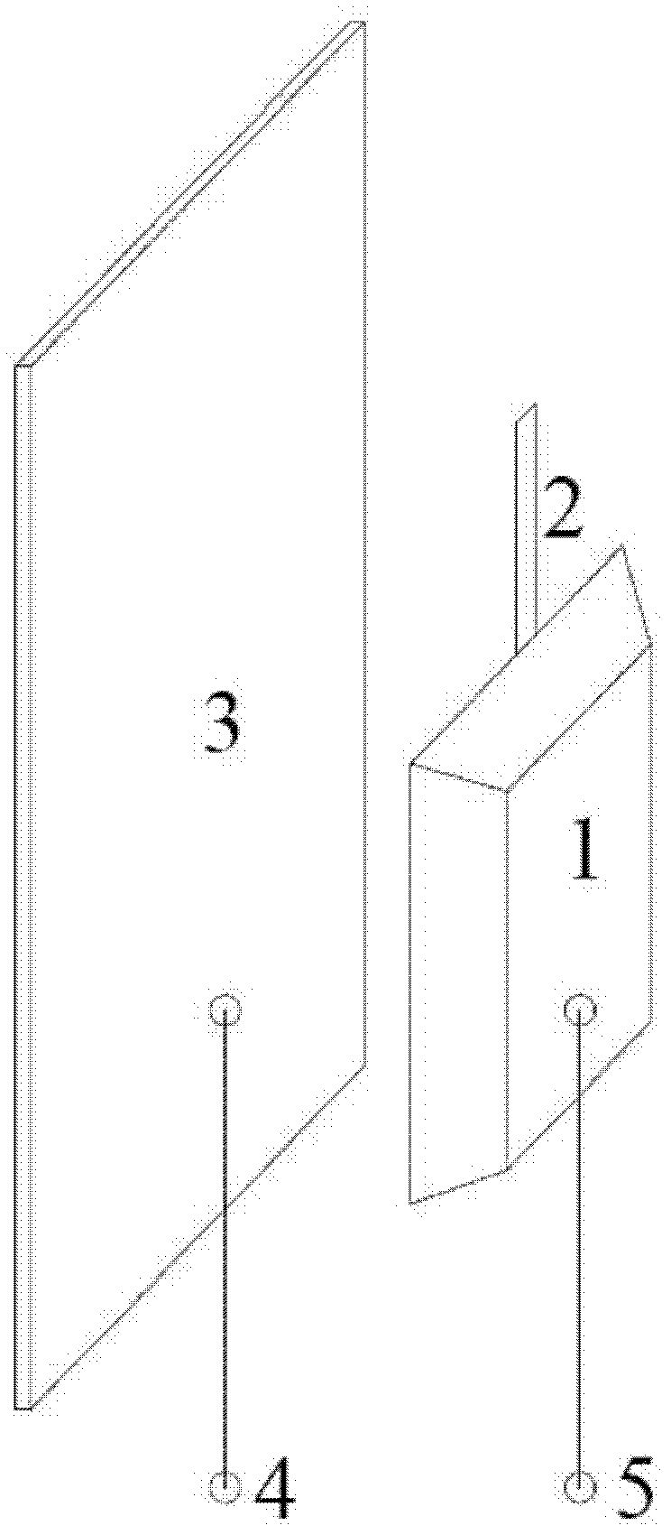
[0025] A microcantilever sensor, such as figure 1 As shown, the micro-cantilever sensor comprises a micro-cantilever base (1) of n-type doped silicon material and a metal electrode (3) placed parallel to the micro-cantilever base; one end of the micro-cantilever base (1) is provided with A needle-free probe (2) of the same material integrated with the base of the micro-cantilever beam, the base of the micro-cantilever beam (1) and the metal electrode (3) are respectively provided with a pulse electric signal access lead (5) and a DC bias connection. Insert the lead wire (4).

[0026] The dimensions of the tipless probe of the microcantilever are 100 microns in length, 20 microns in width, and 1 micron in thickness. The distance between the base of the micro-cantilever beam and the metal electrode is 100 microns.

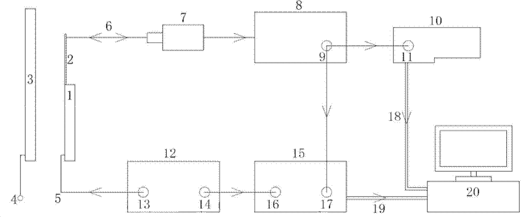
[0027] The resonant excitation method of the above-mentioned micro-cantilever beam sensor is as follows: the signal generator provides a DC voltage signal with an ...

Embodiment 2

[0029] A method for resonance excitation of a micro-cantilever sensor, the structure of the micro-cantilever sensor and its resonance excitation method are the same as those in Embodiment 1, the difference being that:

[0030] The size of the tipless probe of the microcantilever is 200 microns in length, 30 microns in width, and 1.5 microns in thickness. The distance between the base of the micro-cantilever beam and the metal electrode is 500 microns.

[0031] The signal generator provides a DC voltage signal with an amplitude of 8 volts to the metal electrode through the wire on the metal electrode, and at the same time, the signal generator provides a needle-free probe with an amplitude of 8 volts to the micro-cantilever beam through the wire on the base of the micro-cantilever beam. volts, a pulse electrical signal with a bias voltage of 0 volts, and the frequency of the pulse signal is 1 / 7 times the resonance frequency of the micro-cantilever beam probe.

Embodiment 3

[0033] A method for resonance excitation of a micro-cantilever sensor, the structure of the micro-cantilever sensor and its resonance excitation method are the same as those in Embodiment 1, the difference being that:

[0034] The dimensions of the tipless probe of the microcantilever are 300 microns in length, 40 microns in width, and 2 microns in thickness. The distance between the base of the micro-cantilever beam and the metal electrode is 1000 microns.

[0035] The signal generator provides a DC voltage signal with an amplitude of 10 volts to the metal electrode through the wire on the metal electrode, and at the same time, the signal generator provides the micro-cantilever needleless probe with an amplitude of 10 V through the wire on the base of the micro-cantilever beam. volts, a pulse electrical signal with a bias voltage of 0 volts, and the frequency of the pulse signal is 1 / 10 times the resonance frequency of the micro-cantilever beam probe.

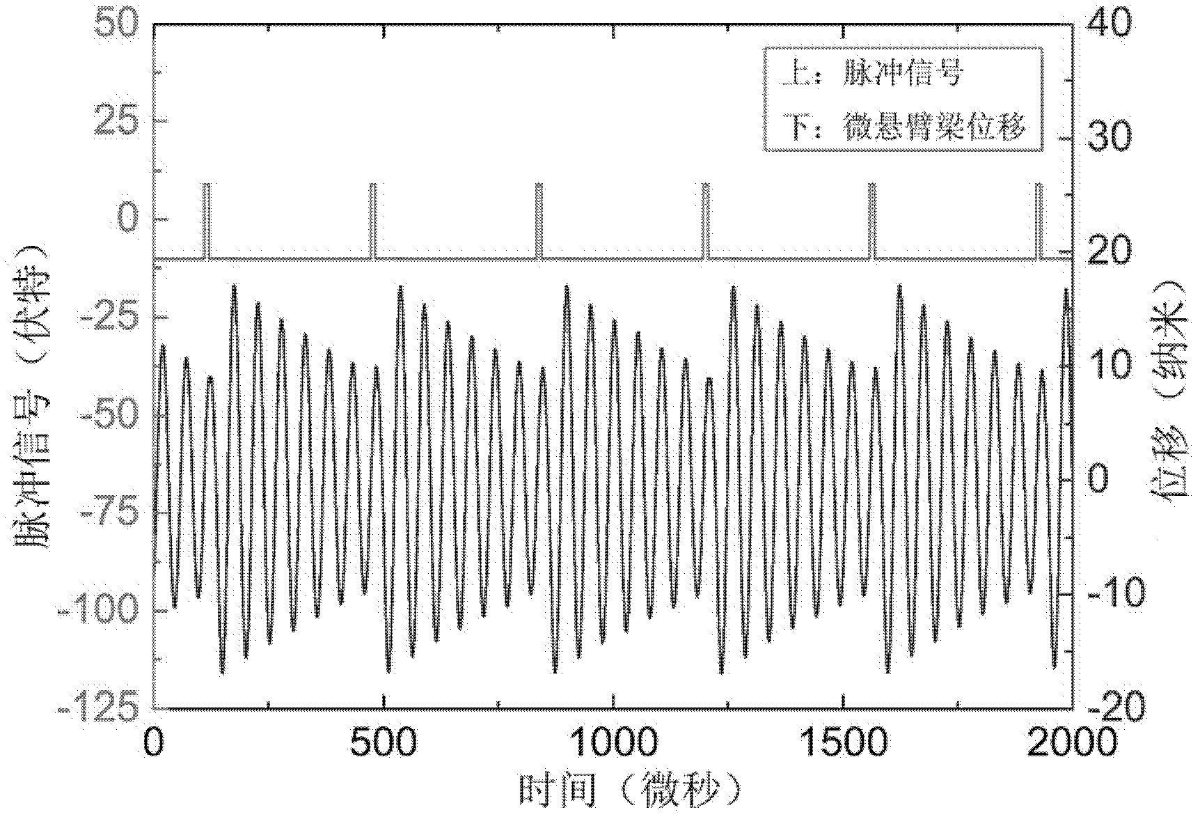
[0036] Such as figu...


PUM


Abstract

A resonance excitation method of a micro-cantilever sensor belongs to the technical field of a micro-motor system. The micro-cantilever sensor is a capacitive micro-cantilever sensor and comprises a micro-cantilever beam base made of a n-type doped silicon material and a metal electrode arranged in parallel to the micro-cantilever beam base, wherein a tipless probe integrated with the micro-cantilever beam base and made of the same material as that of the micro-cantilever beam base is arranged at one end of the micro-cantilever beam base, and a pulse electrical signal ingoing wire and a direct-current biasing voltage ingoing wire are arranged on the micro-cantilever beam base and the metal electrode respectively. The high-frequency resonance of a micro-cantilever beam probe under the excitation with the pulse electrical signal is realized through adding the pulse electrical signal which is fractional times of a micro-cantilever beam probe resonance frequency on the micro-cantilever beam base and adding direct-current biasing voltage on the metal electrode. The resonance excitation method provided by the invention solves the problem that the high-frequency resonance of the micro-cantilever beam probe is difficult to excite, and has an important use value to the development of the micro-cantilever-based sensor.

Description

technical field [0001] The invention relates to a resonance excitation method of a micro-cantilever beam sensor, belonging to the technical field of micro-electromechanical systems. Background technique [0002] The micro-cantilever belongs to a micro-electro-mechanical system (MEMS) with a relatively simple structure, which consists of a base and probes fixed on the base. The probe is usually made of triangular or rectangular silicon or silicon nitride material. According to whether the free end of the probe is provided with a needle point perpendicular to the surface of the probe, the micro-cantilever beam can be divided into a needle-point micro-cantilever beam and a needle-free beam. micro cantilever. For a rectangular probe, its size is tens of microns to hundreds of microns in length, several microns to tens of microns in width, and one to two microns in thickness. The micro-cantilever beam probe has the mechanical characteristics of high resonance frequency and smal...

Claims


Application Information

Patent Timeline
Patent Type & Authority Patents(China)
IPC IPC(8): G01D5/12
Inventor 刘铎冯兆斌
Owner SHANDONG UNIV
Why Eureka
Try Eureka