Device, method and system for detecting energy source gas

A gas detection and energy technology, applied in the measurement of color/spectral characteristics, etc., can solve the problems of small space, difficult detection of non-polar molecular gas samples, inability to meet grading alarms, and downhole concentration warnings, etc., to achieve improved safety. Effect

Inactive Publication Date: 2012-08-01
CHINA UNIV OF PETROLEUM (BEIJING)
View PDF3 Cites 15 Cited by
  • Summary
  • Abstract
  • Description
  • Claims
  • Application Information

AI Technical Summary

Problems solved by technology

2. In terms of mining, H 2 S, H 2 O.CO 2 Such gases have brought adverse effects on many aspects such as life safety and instrument corrosion. For example, when operating natural gas wells, H 2 The detection and alarm method of S gas is very passive and fixed, which cannot meet the important safety requirements such as hierarchical alarm and downhole concentration early warning.
[0007...

Method used


Image

  • Device, method and system for detecting energy source gas
  • Device, method and system for detecting energy source gas
  • Device, method and system for detecting energy source gas

Examples


Embodiment 1

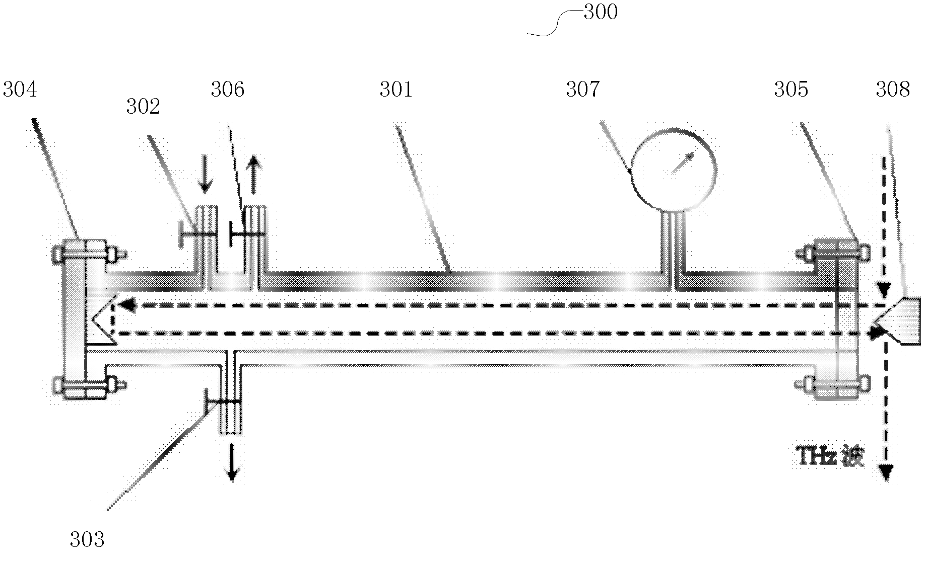
[0025] image 3 It is a cross-sectional view of an energy gas detection device provided by an embodiment of the present invention, as shown in image 3 As shown, the energy gas detection device 300 includes:

[0026] The main cavity 301, the interior of the main cavity 301 is a cylindrical long cavity structure for storing the gas to be detected.

[0027] In the embodiment of the present invention, the interior of the main cavity 301 is a cylinder, and its cross section is approximately a rectangle. The length of the interior of the main cavity 301 may be 30 to 70 mm, and the inner diameter may be 26 to 35 mm. Since the energy gas detection device 300 is mainly used for gas detection in complex environments, the main cavity 301 can be made of alloy material (such as CrNiTi alloy) and the thickness can be 5-9mm, considering the different gas pressures in the downhole and storage and transportation processes. The upper limit of the pressure it can withstand is 14-20MPa.

[00...

Embodiment 2

[0042] Image 6 is a structural diagram of an energy gas detection system provided by an embodiment of the present invention, as shown in Image 6 As shown, the energy gas detection system includes: energy gas detection device 301, double reflective convex mirror 308, signal source device 601, translation platform 602, signal acquisition device 603 and data processing device 604, wherein signal source device 601, signal acquisition device 603 Same as the data processing device 604 and the prior art, a commercially available THz pulse test system can be used, so it will not be repeated here. The translation stage 602, the double-reflecting convex mirror 308 and a series of optical elements form the optical path device 600. In the optical path In the device 600, the double-reflecting convex mirror 308 has been described in the embodiment, and the rest is the same as the prior art, so the specific optical path will not be repeated here.

[0043] In this embodiment of the present...

Embodiment 3

[0046] Figure 7 It is a flow chart of an energy gas detection method provided by the embodiment of the present invention. The energy gas detection method can be realized by using the energy gas detection device and system provided by the embodiment of the present invention, and may specifically include the following steps:

[0047] S701, vacuumize the energy gas detection device.


PUM

PropertyMeasurementUnit
Lengthaaaaaaaaaa
The inside diameter ofaaaaaaaaaa
Thicknessaaaaaaaaaa

Abstract

The invention relates to a device, a method and a system for detecting energy source gas. The device comprises a main cavity, a gas inlet valve and a gas outlet valve, wherein the inside of the main cavity has a cylindrical shape and is used for storing gas to be detected; the gas inlet valve is positioned on the main cavity and used for filling the gas to be detected into the main cavity; the gas outlet valve is positioned on the main cavity and used for discharging the gas to be detected; the two ends of the main cavity have sealing structures; a double-reflection concave mirror is arranged inside the sealing structure at one end; a quartz window is arranged in the middle of the sealing structure at the other end; and terahertz (Thz) wave which is emerged through the quartz window is received by the double-reflection concave mirror, subjected to double reflection and output through the quartz window. By using the device, the method and the system for detecting the energy source gas in the embodiment of the invention, under the condition of not changing the fixed light path of equipment, the problems of narrow detecting space, short light path, low gas cavity pressure resistance and the like in the mainstream Thz experimental equipment at present are solved, and technical support is provided for the Thz measurement of nonpolar molecular gas in the energy source gas.

Description

technical field [0001] The present invention relates to the field of petroleum and petrochemical technology, in particular to the field of energy gas detection technology, in particular to an energy gas detection device, method and system. Background technique [0002] Gas energy such as natural gas, ethylene, acetylene, etc., as one of the main energy types today, has attracted more and more attention. The characterization, detection and detection of energy gases are also becoming more and more important. [0003] As the most typical energy gas, natural gas has been extensively studied in various aspects such as its exploration, exploitation, storage, transportation and use. 1. In terms of exploration, my country has abundant natural gas reserves, and the current proven reserves are about 47-48 trillion cubic meters. Natural gas can be divided into organic and inorganic origin gas according to its origin, and the methods of identification generally include isotope identif...

Claims


Application Information

Patent Timeline
IPC IPC(8): G01N21/25
Inventor 赵昆徐山森田璐
Owner CHINA UNIV OF PETROLEUM (BEIJING)
Why Eureka
Try Eureka