Compact reflective liquid crystal projection light engine system
A liquid crystal projection and reflection technology, applied in the field of light engine system, can solve the problems of high light utilization rate of light engine, low volume and cost, and achieve the effect of volume advantage and light energy utilization rate improvement.
- Summary
- Abstract
- Description
- Claims
- Application Information
AI Technical Summary
Problems solved by technology
Method used
Image
Examples
Embodiment 1
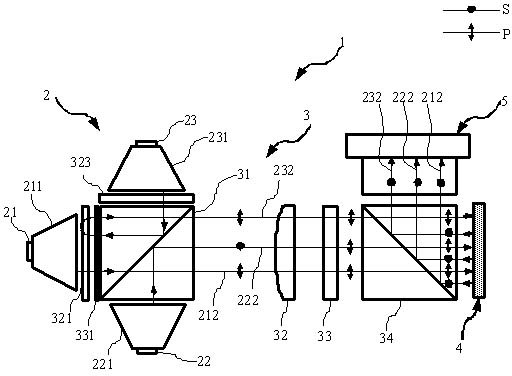
[0028] figure 1 The first embodiment of the compact reflective liquid crystal projection system 1 of the present invention is given, including a light source module 2 , a polarized light management module 3 , an image information module 4 and a projection lens 5 .
[0029] The light source module 2 includes a red light LED 21, a green light LED 22, a blue light LED 23, a green light homogenizer 211, a green light homogenizer 221 and a blue light homogenizer 231, and the red light LED 21 is connected to the red light homogenizer 211 , the green LED 22 is connected to the green homogenizer 221 , and the blue LED 23 is connected to the blue homogenizer 231 .
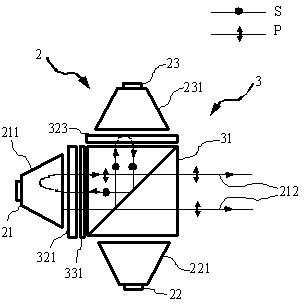
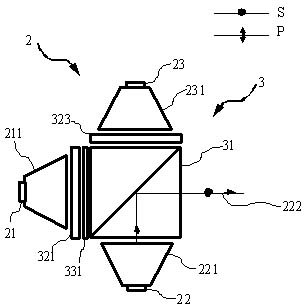
[0030] The natural light of the three primary colors emitted by the red LED 21, the green LED 22 and the blue LED 23 passes through the red light homogenizer 211, the green light homogenizer 221 and the blue light homogenizer 231 respectively, and then collects them into small-angle rectangular light beams required for ligh...
Embodiment 2
[0044] Figure 5 A second embodiment of the compact reflective liquid crystal projection system 1 of the present invention is given. With respect to the first embodiment, in the second embodiment, the positions of the red LED 21 and the red light homogenizing device 211 and the green LED 22 and the green light homogenizing device 221 are reversed, and the blue LED 23 and the blue light homogenizing device 231 are maintained constant. Correspondingly, the green and blue anti-blue filter 322 is used to replace the red and blue anti-blue filter 321, and the blue and green anti-green filter 325 is used to replace the blue and red anti-filter 323. This embodiment can realize the reuse of green light, the green light emitted from the first PBS 31 is in P polarization state, and the red light and blue light are in S polarization state. At this time, the polarization interference filter 33 should select half-wave rotated green light while keeping the polarization state of red light ...
Embodiment 3
[0046] Figure 6 A third embodiment of the present invention is given. Compared with the first embodiment, the difference of this embodiment is that the polarization color combining unit consists of a first PBS 31, a red-transmitting and blue-transmitting filter 321, a green-transmitting blue filter 322, a blue-transmitting red-green The optical filter 324 and the broadband quarter-wave plate 331 are composed.
[0047] The broadband quarter-wave plate 331 and the second broadband quarter-wave plate 332 are respectively glued to the red light incident surface and the green light incident surface of the first PBS 31, and then respectively bonded to the red and anti-blue filter 321 Glue with the green and anti-blue filter 322 , the red and anti-blue filter 321 is located on the red light incident surface of the first PBS 31 , and the green and anti-blue filter 322 is located on the green light incident surface of the first PBS 31 . The blue-transparent anti-red-green filter 324...
PUM
 Abstract
Description
Claims
Application Information
 - R&D
- Intellectual Property
- Life Sciences
- Materials
- Tech Scout
- Unparalleled Data Quality
- Higher Quality Content
- 60% Fewer Hallucinations
Browse by: Latest US Patents, China's latest patents, Technical Efficacy Thesaurus, Application Domain, Technology Topic, Popular Technical Reports.
© 2025 PatSnap. All rights reserved.Legal|Privacy policy|Modern Slavery Act Transparency Statement|Sitemap|About US| Contact US: help@patsnap.com


