
Multi-aperture interference imaging method

An interferometric imaging and multi-aperture technology, applied in special data processing applications, measuring devices, instruments, etc., can solve the problems of restoring image contrast loss, affecting imaging image quality, and inability to obtain spatial frequency, etc., and achieve the effect of reducing the load burden

Active Publication Date: 2021-01-29
CHANGCHUN INST OF OPTICS FINE MECHANICS & PHYSICS CHINESE ACAD OF SCI
View PDF3 Cites 2 Cited by
  • Summary
  • Abstract
  • Description
  • Claims
  • Application Information

AI Technical Summary

Problems solved by technology

This apodization effect makes it impossible to obtain information with a spatial frequency lower than D / λ, and the approximate shape of the observed object is determined by the low-frequency signal, so the contrast of the restored image will be greatly lost, thereby affecting the image quality of the image.

Method used


Image

  • Multi-aperture interference imaging method
  • Multi-aperture interference imaging method
  • Multi-aperture interference imaging method

Examples


Embodiment Construction

[0059] The present invention will be described in further detail below in conjunction with the accompanying drawings and specific embodiments.

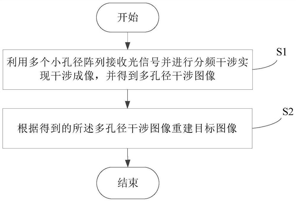
[0060] refer to figure 1 Shown is a flow chart of a preferred embodiment of the multi-aperture interference imaging method of the present invention.

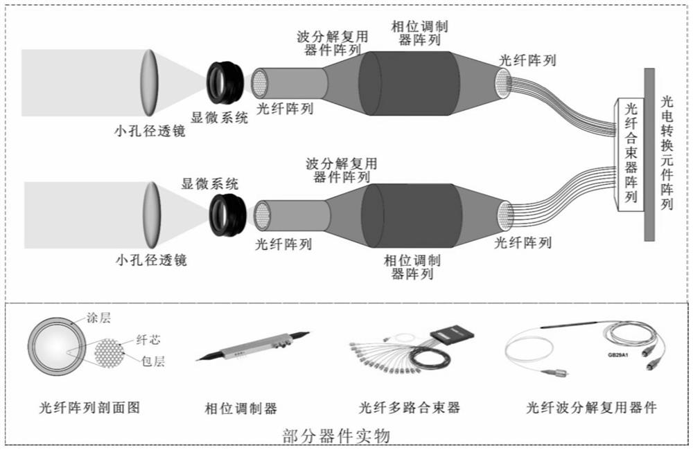
[0061] Step S1, using multiple small aperture arrays to receive optical signals and perform frequency division interference to achieve interference imaging (please refer to figure 2 ), and obtain the multi-aperture interference image.

[0062] Specifically, step S1 includes:

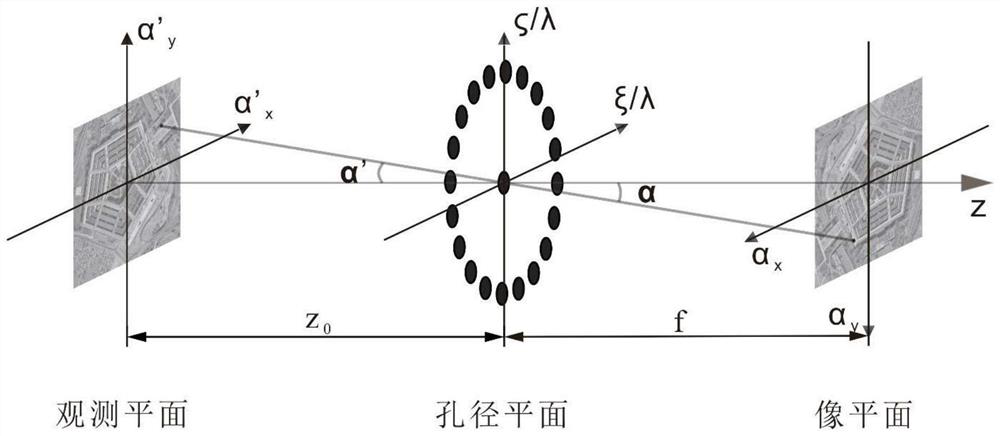
[0063] Step S11, using the partial coherence theory to describe the process of the far-field incoherent source light propagating from the observation plane to the aperture plane, and obtaining the cross-spectral density function on the aperture plane.

[0064] Such as image 3 As shown, in this embodiment, the partial coherence theory is used to describe the process of the far-field incoherent source light pr...


PUM


Abstract

The invention relates to a multi-aperture interference imaging method. The method comprises the following steps of: a, receiving an optical signal by using a plurality of small-aperture arrays, performing frequency division interference to realize interference imaging of the optical signal from an observation plane to an aperture plane to an image plane, and calculating to obtain a multi-apertureinterference image; and b, reconstructing a target image according to the obtained multi-aperture interference image. According to the invention, the imaging quality can be obviously improved, the in-phase adjustment difficulty of the imaging system is reduced, and the size, power consumption and weight of the system are greatly reduced.

Description

technical field [0001] The invention relates to a multi-aperture interference imaging method. Background technique [0002] In the prior art, the general imaging system based on the principle of precise refraction is composed of an imaging objective lens group and an array of photoelectric conversion devices. The object light enters the imaging objective lens group, and the formed image is received by the photoelectric conversion device array to obtain an object image. Through the imaging system, it can Record and observe the shape of objects in real time. The basic design principle of traditional optical telescopes is still based on the design concept of precise refraction. Constrained by the diffraction limit, in order to improve the resolution, the system aperture must be increased. In order to achieve higher resolution, the volume and weight of traditional space telescopes are extremely large: for example , the primary mirror of the Hubble Space Telescope has an apertur...

Claims


Application Information

Patent Timeline
IPC IPC(8): G01B11/24G06F30/20
CPCG01B11/2441G06F30/20
Inventor 曾雪锋陈天宝张学军白莹莹张峰张志宇
Owner CHANGCHUN INST OF OPTICS FINE MECHANICS & PHYSICS CHINESE ACAD OF SCI
Learn More