Preparation method of multilayer ceramic antenna

A multi-layer ceramic and antenna technology, which is applied in the field of microwave component design and manufacture, can solve the problems of reducing production efficiency, interconnecting influence, increasing cost, etc., and achieves the effects of low processing accuracy requirements, product cost reduction, and processing difficulty reduction.

Inactive Publication Date: 2014-04-09
UNIV OF ELECTRONICS SCI & TECH OF CHINA
View PDF5 Cites 2 Cited by
  • Summary
  • Abstract
  • Description
  • Claims
  • Application Information

AI Technical Summary

Problems solved by technology

The first method needs to punch a large number of holes on the tiles, and only one tile can be punched at a time, which is very inefficient. When large-scale processing is performed, the drilling process takes a lot of time and seriously reduces production efficiency; the second method saves Holes are punched, but additional screen printing is required on the side, which not only increases the cost, but also the screen must be precisely aligned with the screen on the surface. Once the alignment deviates, the interconnection will be affected, or even the interconnection will not be possible.

Method used


Image

  • Preparation method of multilayer ceramic antenna
  • Preparation method of multilayer ceramic antenna
  • Preparation method of multilayer ceramic antenna

Examples


Embodiment 1

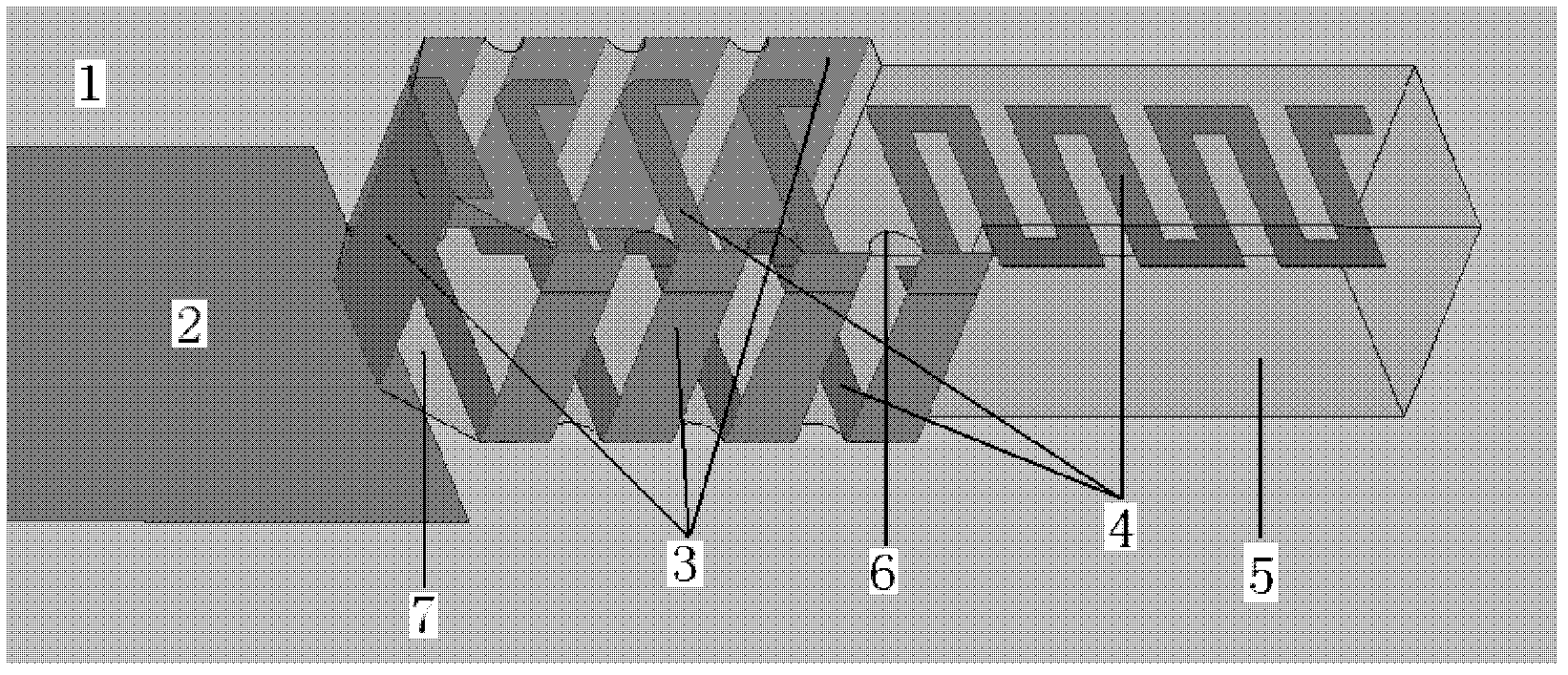
[0026] The multilayer ceramic antenna structure of Embodiment 1 is as figure 1 As shown: it includes ceramic medium 5 and multilayer radiation conductor strip 4 in ceramic medium 5, and also includes peripheral sealing metal 3 and edge isolation hole 6, and said edge isolation hole 6 connects the multilayer radiation conductor strip 4 The vertical overlapping portion protrudes from the surface of the ceramic medium and is used to isolate the adjacent peripheral termination metal 3 , which is used for the interlayer interconnection of the multilayer radiation conductor ribbon 4 .

[0027] The multilayer ceramic antenna here also includes an edge chamfer 7 arranged on the feeding surface of the ceramic medium 5, and the vertical overlapping part of the radiation conductor strip 4 and the external microstrip feeder 2 protrudes from the surface of the ceramic medium 5 for the radiation conductor Strip 4 is electrically connected to the external microstrip feeder 2 .

[0028] fig...

Embodiment 2

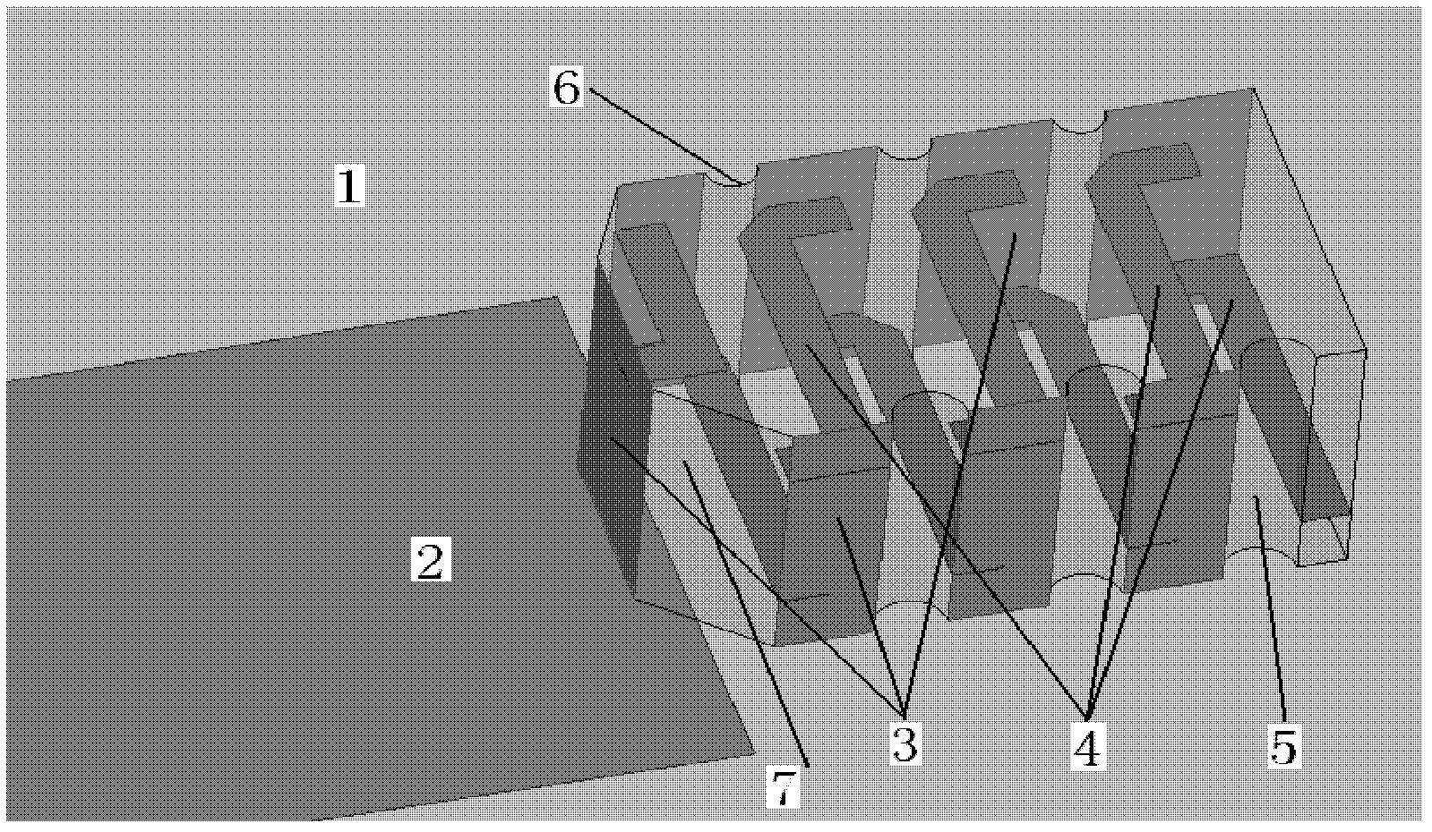
[0030] The multilayer ceramic antenna structure of embodiment two is as figure 2 Shown: similar to Example 1, including ceramic medium 5 and two layers of radiating conductor strips 4 located in ceramic medium 5, and also including peripheral sealing metal 3 and edge isolation hole 6, and ceramic medium 5 is stacked with two layers from top to bottom. A layer of radiating conductors 4, two layers of radiating conductors overlapped up and down together to form a serpentine curved antenna. According to the same idea, by simultaneously punching holes and cutting corners at the appropriate position on the peripheral edge of the vertically aligned LTCC components, the ceramic medium at the vertical overlap of the upper and lower conductors is protruded, so that it is convenient to connect the two conductors and the feeder through sealing .

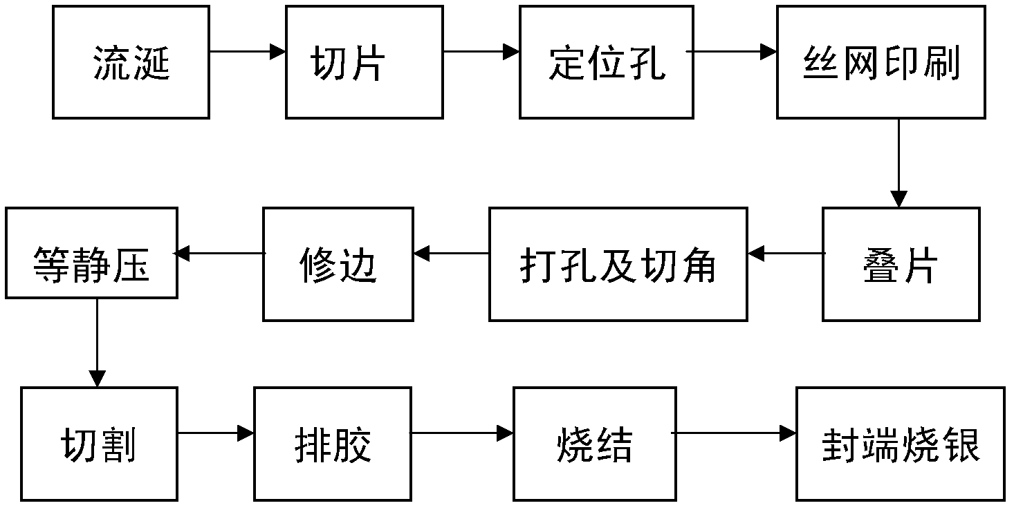
[0031] The technological process adopted by the specific implementation example of the present invention is as image 3 As shown, it specif...


PUM


Abstract

The invention discloses a multilayer ceramic antenna and a preparation method thereof. The ceramic antenna comprises a ceramic medium and multiple layers of radiating conductor belts positioned in the ceramic medium, and is characterized in that the ceramic antenna further comprises peripheral end sealing metal and edge isolating holes, wherein by adopting the edge isolating holes, vertical overlapping parts of the multiple layers of radiating conductor belts protrude from the surface of the ceramic medium; the edge isolating holes are used for isolating adjacent peripheral end sealing metal; and the peripheral end sealing metal is used for interconnecting the multiple layers of radiating conductor belts. The multilayer ceramic antenna disclosed by the invention has the advantages that through the isolating holes and chamfers positioned in appropriate positions of the edge of the periphery of the ceramic medium, the vertical overlapping parts of the multiple layers of radiating conductor belts and the vertical overlapping parts of the multiple layers of radiating conductor belts with an external micro strip feeder line are enabled to protrude from the surface of the ceramic medium and be isolated from each other, and the multiple layers of connectors can be conveniently connected through the end sealing metal, thereby realizing the interconnection among different metal layers under the circumstance that a through-hole is not needed; and besides, a large quantity of ceramic media can be stacked to be edge-punched and chamfered at once.

Description

technical field [0001] The invention belongs to the technical field of design and manufacture of microwave components, and in particular relates to the design of a multilayer ceramic antenna and a preparation method thereof. Background technique [0002] As an important part of the RF front-end in a wireless communication system, the antenna plays an important role in the design of the entire wireless communication system. The antenna plays the main role of receiving and transmitting electromagnetic signals in the system, and its performance is directly related to the overall operation of the communication system. With the increasing shortage of wireless spectrum resources and the trend of increasingly smaller size and more diversified functions of mobile terminal equipment, it is often necessary to integrate multiple antennas in a single mobile terminal, which makes the requirements of high performance, low cost and miniaturization of antennas become focus of the designer'...

Claims


Application Information

Patent Timeline
Patent Type & Authority Patents(China)
IPC IPC(8): H01Q1/38H01Q1/50
Inventor 唐伟韩世雄许宏志卢宁左丽花
Owner UNIV OF ELECTRONICS SCI & TECH OF CHINA
Why Eureka
Try Eureka