Method and system for realizing optical fibre interconnection based on SAS/SATA interface
A technology of SATA interface and implementation method, which is applied in the field of internal interconnection of storage devices, can solve problems such as output uncertainty, Idle signal optical fiber transmission, and vibration, and achieve the effects of simple structure, flexible system, and improved efficiency
- Summary
- Abstract
- Description
- Claims
- Application Information
AI Technical Summary
Problems solved by technology
Method used
Image
Examples
Embodiment 1
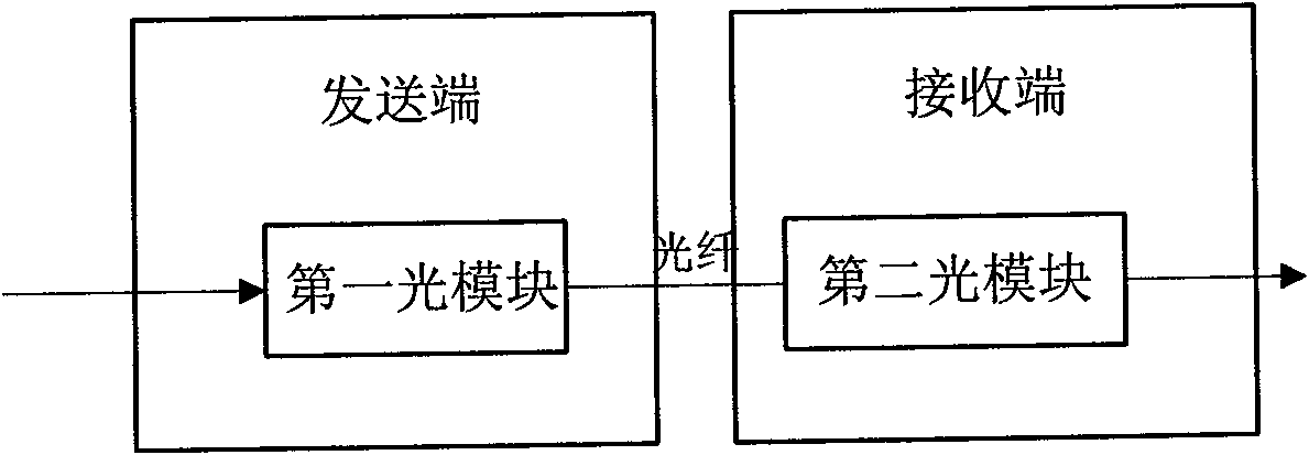
[0062] In this example, the second signal processing module can be specifically implemented as Figure 8 The structure shown further includes a detection unit, a first receiving buffer, a first sending buffer, a first serial-to-parallel conversion unit, a second serial-to-parallel conversion unit, and a custom coding or primitive unit. The detection unit detects the Idle signal of the standard SAS interface, and the digital sequence of the SAS standard is directly placed in the first transmission buffer TxBuffer for transmission. Coding or custom primitives convert it into a custom digital sequence that can be transmitted by the optical fiber, insert the custom digital sequence into the corresponding position of the first transmission buffer TxBuffer of the optical port during the Idle signal time, and then send it through the second serial And the conversion unit sends to the first optical module for optical fiber transmission.
[0063] The third signal processing module can...
Embodiment 2
[0065] The second signal processing module is also used to detect the OOB signal, and replace the detected OOB signal with a custom primitive or a data frame composed of a custom primitive, and send the processed OOB signal to the receiving end; The three signal processing modules are also used to detect the OOB signal, and restore the original OOB signal when it detects that there is a custom primitive or a data frame composed of the custom primitive.
[0066] In this example, the second signal processing module and the third signal processing module can be specifically implemented as Figure 10 In the structure shown, the encoding / analysis unit in the second signal processing module detects and analyzes the OOB signal, and uses a custom primitive or a data frame composed of a custom primitive to replace the corresponding OOB, such as COMMINIT, COMMREST, COMSAS, COMWAKE, Put it into the second sending buffer TxBuffer of the optical port for sending, and then pass through the ...
Embodiment 3
[0068] Such as Figure 11 As shown, the sending end includes a first embedded processor, which is used to replace the corresponding OOB function with a data frame composed of custom codes or primitives or custom primitives, and send the digital sequence to the receiving end; the receiving end includes The second embedded processor is used to detect the digital sequence, and when detecting the presence of custom coding or primitives or data frames composed of custom primitives, perform negotiation processing according to the corresponding out-of-band signal negotiation process defined by the SAS standard .
[0069] The first embedded processor and the second embedded processor in this example can be implemented as Figure 12 structure shown. At present, the SAS Initiator (HBA: Host Bus Adapter) and SAS Expander designed by storage IC manufacturers all use embedded processors (such as ARM, MIPS), use firmware (Firmware) to control the work of the chip, and can directly control...
PUM
 Abstract
Description
Claims
Application Information
 - R&D
- Intellectual Property
- Life Sciences
- Materials
- Tech Scout
- Unparalleled Data Quality
- Higher Quality Content
- 60% Fewer Hallucinations
Browse by: Latest US Patents, China's latest patents, Technical Efficacy Thesaurus, Application Domain, Technology Topic, Popular Technical Reports.
© 2025 PatSnap. All rights reserved.Legal|Privacy policy|Modern Slavery Act Transparency Statement|Sitemap|About US| Contact US: help@patsnap.com


