Magnetic valve controllable reactor

A reactor and magnetic valve type technology, applied in the field of magnetic valve type controllable reactors, can solve the problems of increased installation workload, magnetic flux leakage, large fuel tank volume, etc., to avoid partial discharge, compact overall structure, and simplify the wiring process Effect

Inactive Publication Date: 2012-08-01
STATE GRID SHANDONG ELECTRIC POWER +1
View PDF5 Cites 5 Cited by
  • Summary
  • Abstract
  • Description
  • Claims
  • Application Information

AI Technical Summary

Problems solved by technology

[0012] 1. The existing reactor adopts an iron fuel tank, and the magnetic flux leakage is relatively large during operation, and the wall of the fuel tank will generate eddy current loss. If necessary, a magnetic shield must be added to the tank wall, resulting in an increase in the volume of the fuel tank
[0013] 2. Secondly, the top outlet of the existing reactor adopts the outlet column, and the iron fuel tank needs to use two 72kV high-voltage bushings, so that the height of the fuel tank increases
Uneven field strength, easy to cause partial discharge
[0014] 3. Due to the existence of magnetic flux leakage during operation, the bottom and cover of the iron fuel tank are overheated
[0015] 4. The installation of the thyristor is usually installed outside the reactor, and the reactor is large in size, which puts forward higher and more requirements for the site and insulation, and also increases the installation workload
[0016] 5. In reality, there are many analytical works on reactors in theory, but few are actually put into practice, especially in the field of high voltage or extra high voltage and the fields with higher requirements for insulation.
[0017] 6. Most of the existing reactors are controlled by optical fiber communication. In actual use, the requirements for operators are high, and the wiring is complicated, which makes maintenance difficult.

Method used


Image

  • Magnetic valve controllable reactor
  • Magnetic valve controllable reactor
  • Magnetic valve controllable reactor

Examples


Embodiment Construction

[0064] The present invention will be further described below in conjunction with the accompanying drawings and embodiments.

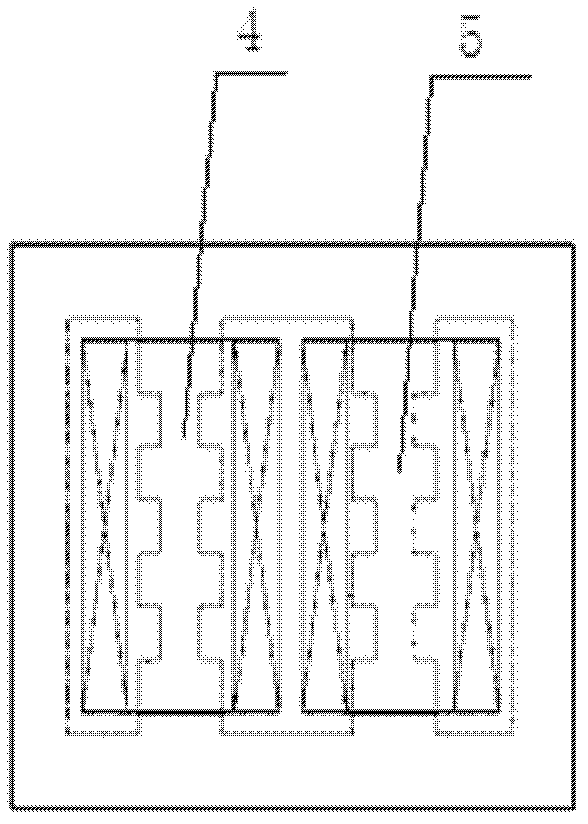
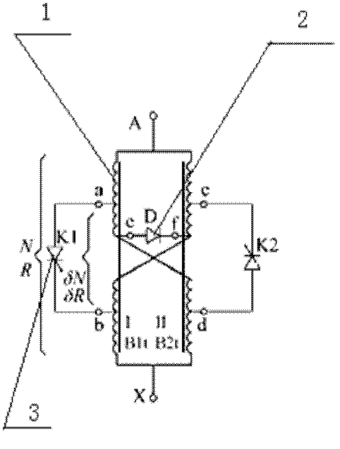
[0065] Figure 1A is a structural diagram of a single-phase MCR; Figure 1B is a schematic diagram of the principle of a single-phase MCR;

[0066] The magnetic valve type controllable reactor of the present invention has no side yoke structure, which constitutes a two iron core structure controllable reactor. The yoke constitutes a four-column iron core structure. The iron core structure of the present invention is a double iron core, and the side yokes on both sides are used at the top. There are only cross yokes connecting the two iron core columns, and there are double iron cores, as shown in Figures 1A and 1B. Coils are wound around each iron core column to form two main coils; at least one small section section is respectively arranged on the iron core column I 4 and II, and the upper and lower sides of the iron core column I 4 are respectively woun...


PUM

PropertyMeasurementUnit
heightaaaaaaaaaa

Abstract

The invention discloses a magnetic valve controllable reactor, which comprises an outer insulating barrel. An upper end cover part is arranged at the upper end of the outer insulating barrel, and the lower end of the outer insulating barrel is connected with a lower end cover part. The upper end cover part comprises a high-voltage terminal of the reactor and an upper end cover, and the lower end cover part comprises a low-voltage terminal of the reactor, a pulse control line terminal and a lower end cover. A reactor main body is fixed on the inner surface of the lower end cover. A main winding of the reactor is connected with the high-voltage terminal and low-voltage terminal of the reactor respectively. An insulating bracket is arranged at the upper end of a reactor core. A thyristor component and a pulse transformer are arranged on the insulating bracket, and are connected with each other. The pulse transformer is connected with the pulse control line terminal. The invention has the advantages that: the magnetic valve controllable reactor is simple in manufacturing process, low in cost and loss, small in harmonics and wide in voltage application range, and has application potential of improving the transmission capability, regulating the voltage of a power grid, compensating reactive power and limiting over-voltage.

Description

technical field [0001] The invention relates to a reactor, in particular to a magnetic valve type controllable reactor. Background technique [0002] Static Var Compensator (SVC) is a kind of fast reactive power adjustment device developed abroad in the 1970s, and has been successfully applied to the compensation of loads such as electrified railways, metallurgy, electric power, mining and high-energy accelerators. This type of device has obvious advantages over synchronous condensers in terms of speed of adjustment, variety of functions, reliability of work, economy of investment and operating costs, etc., and can obtain better technical and economic benefits. Therefore, it is popular at home and abroad. Has achieved rapid development. [0003] There are three main types of mainstream SVC: Thyristor Switched Capacitor (TSC for short), Thyristor Controlled Reactor (TCR for short), and Magnetic valve Controllable Reactor (MCR for short). [0004] TSC has simple control, low...

Claims


Application Information

Patent Timeline
Patent Type & Authority Applications(China)
IPC IPC(8): H02J3/18H01F29/00H01F27/30H01F27/26H01F27/40H01F27/29
CPCY02E40/30
Inventor 张连宏贾传斌于洪李永宁谭京一林冬晧孙英涛周迎新杨琦欣仝瑞士
Owner STATE GRID SHANDONG ELECTRIC POWER
Why Eureka
Try Eureka