Drawing compound molding die for shell with tooth form on side wall

A compound forming and tooth shape technology, applied in the field of machinery, can solve problems such as limited popularization, complex mold structure, and difficult-to-form parts, and achieve the effects of reducing production costs, simplifying mold structure, and reducing forming force

Inactive Publication Date: 2012-08-08
SHANGHAI JIAO TONG UNIV +1
View PDF5 Cites 19 Cited by
  • Summary
  • Abstract
  • Description
  • Claims
  • Application Information

AI Technical Summary

Problems solved by technology

[0004] But all there is certain limitation in above-mentioned these methods, then there are following deficiencies as above-mentioned method is used for the casing part of side wall band tooth shape of the present invention: (1) spinning process needs special-purpose equipment, general enterprise cannot Adoption, at the same time limited by the wall thickness of the parts, which largely limits its promotion and use
(2) The forming force of the bulging process is too large, and the mold structure is complex, the mold is easily damaged, and there are high requirements for the mold material, structure and life, and it is difficult to form small-sized parts
(3) The thinning and deep drawing process is relatively simple and is a commonly used process, but the cup-shaped part is formed first, and then the tooth shape is formed at another station, resulting in more forming processes

Method used


Image

  • Drawing compound molding die for shell with tooth form on side wall
  • Drawing compound molding die for shell with tooth form on side wall
  • Drawing compound molding die for shell with tooth form on side wall

Examples


Embodiment Construction

[0024] The technical solution of the present invention will be described in further detail below in conjunction with the examples. This embodiment is based on the premise of the technical solution of the present invention, providing detailed implementation and specific operation process, but the protection scope of the present invention is not limited to the following implementation example.

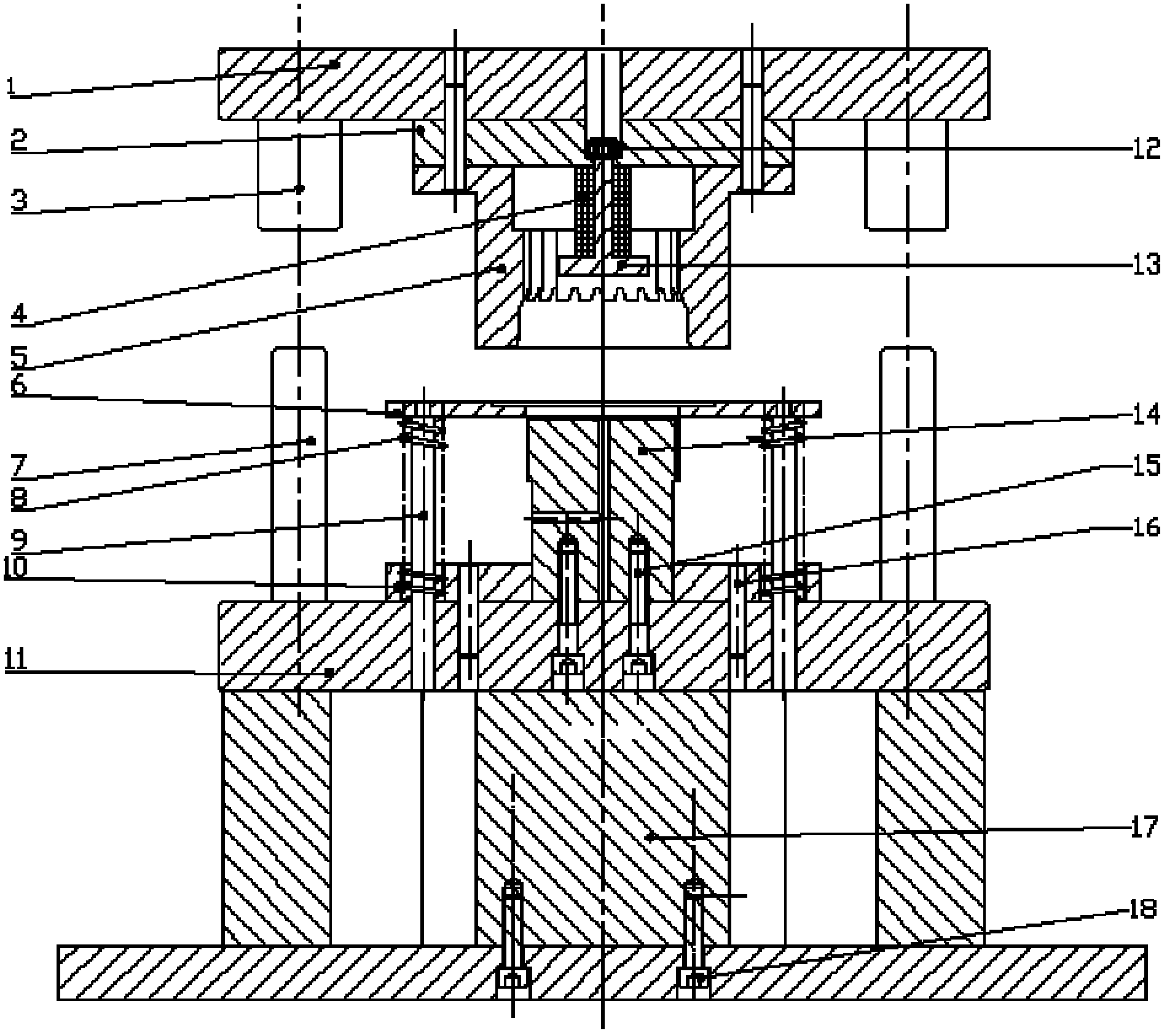
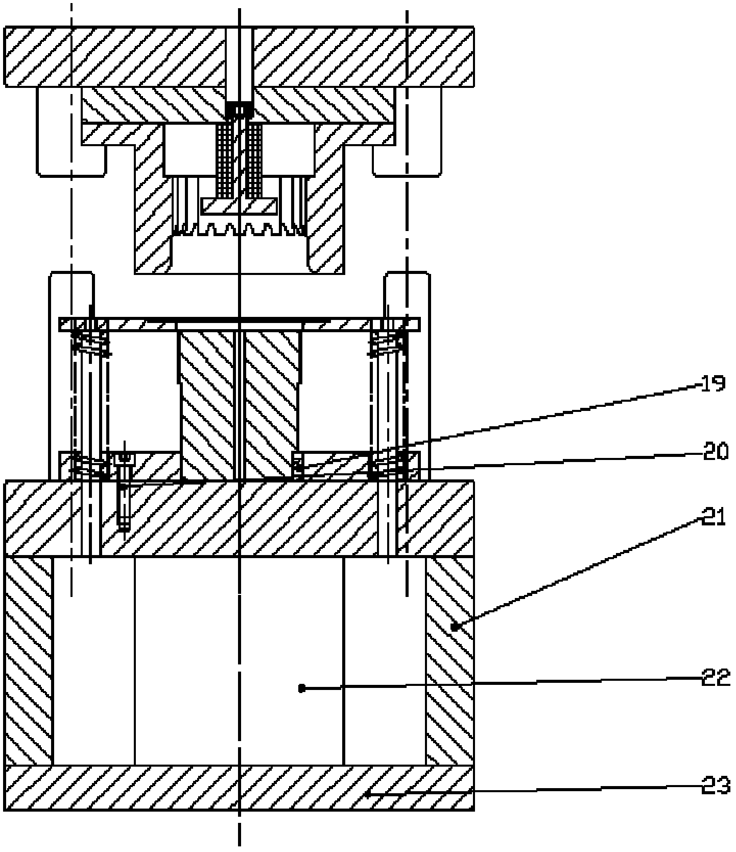
[0025] Please also see figure 1 and figure 2 The structure schematic diagram of the present invention shows that the drawing compound forming mold for the toothed shell on the side wall includes an upper mold part and a lower mold part capable of relative movement.

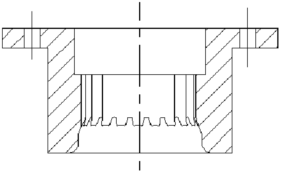
[0026] The upper mold part includes an upper mold base 1, a backing plate 2, a top piece device and a die 5. A guide sleeve 3 is arranged on the upper mold base 1 . The die 5 is fixed on the upper die base 1 through the backing plate 2 by pins, and the backing plate 2 is sandwiched between the upper die base 1 and the di...


PUM


Abstract

The invention discloses a drawing compound molding die for a shell with a tooth form on a side wall. The drawing compound molding die comprises an upper die component and a lower die component which can move relatively, wherein the upper die component comprises an upper die holder and a female die fixed on the upper die holder; the lower die component comprises a lower die holder and a male die fixed on the lower die holder; the female die is provided with an inner die cavity for molding the shell; the inner die cavity comprises a lower drawing section and an extruding section which extends upwards; the drawing section is cylindrical, and is in smooth transition with the extruding section; the circumferential wall of the extruding section is provided with a tooth form; the male die is cylindrical, and can extend into the inner die cavity of the female die; and the circumferential wall of the male die is provided with a tooth form which corresponds to the tooth form of the extruding section. The drawing compound molding die has the advantages of simple structure, easiness for assembling, low molding force and long service life, and is suitable for drawing and molding a shell part with a tooth form on a side wall.

Description

technical field [0001] The invention relates to a forming die, in particular to a drawing composite forming die for a toothed shell workpiece on a side wall, belonging to the technical field of machinery. Background technique [0002] Housing parts with toothed side walls are widely used in mechanical parts. The most common application example is the automobile clutch housing. The two ends of the clutch housing are respectively connected with the gearbox body and the engine, supporting the transmission. At the same time, it bears a large torque, and its precision and quality directly affect the performance of the car. [0003] At present, no relevant patents have been found for the molding of the shell workpiece with toothed side walls. In terms of academic research, Dong Hongbo of Nanchang Hangkong University (Forging Technology, 2009, 34(4): 32-36) used powerful spinning equipment to process cup-shaped internal gears, and simulated its forming process. This method is appl...

Claims


Application Information

Patent Timeline
Patent Type & Authority Applications(China)
IPC IPC(8): B21D37/10B21D22/20B21D45/10
Inventor 赵震夏汉关庄新村赵红军夏敏董义向华袁鹏
Owner SHANGHAI JIAO TONG UNIV
Why Eureka
Try Eureka