

Resin composition
A resin composition, resin technology, applied in the direction of layered products, metal layered products, printed circuit parts, etc.
- Summary
- Abstract
- Description
- Claims
- Application Information
AI Technical Summary
Problems solved by technology
Method used
Image

Examples
Embodiment 1
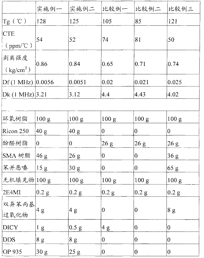
[0032] A 20% vinyl-toluene solution was prepared by dissolving 40 g of Ricon 250 in 160 g of toluene. Add 100g biphenyl epoxy resin, 46g SMA resin, 15g benzoxazine, 90g aluminum hydroxide, 10g talc, 4g dicumyl peroxide, 1g dicyandiamide (DICY), 8g diamino diphenyl sulfone (DDS), 30g OP 935, 1g TSH, 0.2g 2E4MI, and then add 200g vinyl-toluene solution into the aforementioned reaction flask to prepare Completely dispersed epoxy resin main agent.
Embodiment 2
[0034] A 20% vinyl-toluene solution was prepared by dissolving 40 g of Ricon 250 in 160 g of toluene. Add 100g biphenyl epoxy resin, 26g SMA resin, 30g benzoxazine, 90g aluminum hydroxide, 10g talcum powder, 4g diisophenylpropyl peroxide, 0.5gDICY, 8g DDS, 25g OP 935, 1.5g TSH, 0.2g 2E4MI, and then add 200g vinyl-toluene solution into the aforementioned reaction bottle to prepare the dispersed epoxy resin main agent.
Embodiment 3
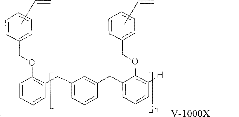
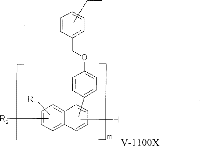
[0047] A 20% vinyl-toluene solution was prepared by dissolving 40 g of Ricon 250 in 160 g of toluene. Add 100g of biphenyl epoxy resin, 20g of V-1100X resin, 15g of benzoxazine, 16g of SMA resin, 90g of aluminum hydroxide, 10g of talc, and 4g of diisophenylpropyl peroxide into a 1000mL reaction bottle , 1g DICY, 8g DDS, 40g OP 935, 1g TSH, 0.2g 2E4MI, and then add 200g vinyl-toluene solution into the aforementioned reaction bottle to prepare the dispersed epoxy resin main agent.
PUM
| Property | Measurement | Unit |
|---|---|---|
| particle diameter | aaaaa | aaaaa |
Abstract
Description
Claims
Application Information