Heat exchange plate layer structure and manufacturing method of freeze drier

A technology of heat exchange plate and manufacturing method, which is applied in the field of manufacturing and processing, with good heat exchange performance, can solve the problems of large amount of welding on the back of the plate, leakage of the plate, amazing welding heat, etc., and achieve the effect of simple internal structure and manufacturing method

Inactive Publication Date: 2012-08-15
SHANGHAI SUPARMIN ELECTROMECHANICAL SCI & TECH CO LTD
View PDF0 Cites 4 Cited by
  • Summary
  • Abstract
  • Description
  • Claims
  • Application Information

AI Technical Summary

Problems solved by technology

Rectangular spacers are used inside the board, and the spacer and the upper board are normally argon arc welded, but the lower board must be punched and welded on the bottom board to form the board, which has the following disadvantages: the back of the board is welded The amount is very large, the welding heat is amazing, and the deformation of the back plate is terrible. In the later stage of the production of the plate, a lot of grinding work needs to be done on the back of the plate. Sometimes the solder joints will be worn out during grinding, causing the plate to leak
The temperature of the board layer is very uneven
There are a lot of solder joints on the back of the board, and the flatness of the board is very bad

Method used


Image

  • Heat exchange plate layer structure and manufacturing method of freeze drier

Examples


Embodiment Construction

[0015] The present invention will be further described below in conjunction with accompanying drawing:

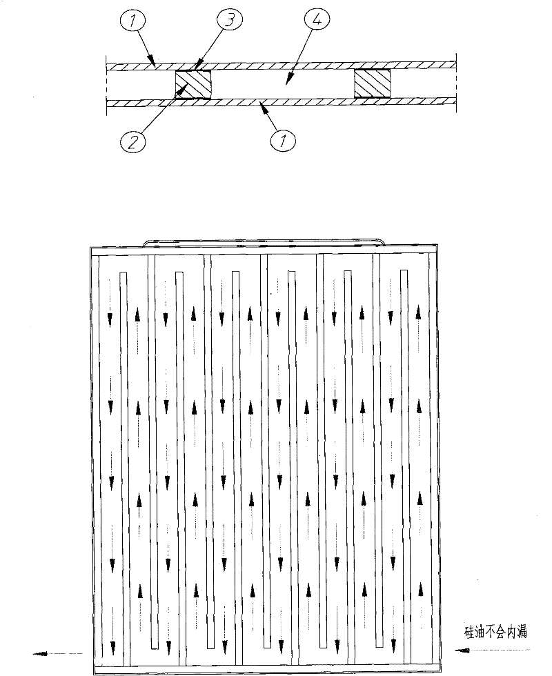
[0016] See attached figure 1 , between the upper and lower bottom plates 1 and the spacers 2 placed at intervals, there is a sealing structure in which copper and platinum 3 are brazed into one body, and the space between the upper and lower bottom plates 1 and the spacers 2 is filled with silicone oil 4 .

[0017] See attached figure 1 , put copper platinum 3 between the upper and lower bottom plates 1 and the spacers 2 placed at intervals, the copper platinum 3 is placed according to the direction of the attached drawing, clamped with a fixture, and put into a vacuum brazing furnace. The high temperature in the furnace will melt the copper platinum 3. During the brazing process, the vacuum pump will suck all the air, including the air between the upper and lower bottom plates 1 and the copper platinum 3, copper platinum 3 and the spacer 2, and the vacuum brazing furnace ...


PUM


Abstract

The invention relates to a heat exchange plate layer structure and a manufacturing method of a freeze drier. The heat exchange plate layer structure is characterized in that an integral seal structure formed by the welding of copper-platinum brazing is arranged among upper and lower bottom plates and division bars which are arranged at intervals. The manufacturing method comprises the steps of: placing copper platinum among the upper and lower bottom plates and the division bars which are arranged at intervals, clamping the copper platinum by using a clamp, putting the copper platinum into a vacuum brazing furnace and melting the copper platinum at high temperature, implementing vacuum on the vacuum brazing furnace in a process, melting the copper platinum when the brazing temperature is achieved, cooling, and then pouring silicone oil so as to form the heat exchange plate layer structure of the freeze drier. The heating of local parts caused by welding does not exist, the plate layer transformation is small, the smoothness is good, the heat exchange plate layer structure is beneficial to polishing and reshaping, the division bars and the upper and lower bottom plates are closely spliced, the welding is good, and silicone oil can not be in short circuit so as to avoid fleeing to the other side of the plate layer directly from the upper parts or the lower parts of the division bars; the temperature of the plate layer is very uniform, the welding is conducted in the plate layer, so that the influence on the exterior of the plate layer is low, and the smoothness of the plate layer is guaranteed; and the welding seams are arranged in the plate layer, and the whole plate does not have holes and gaps and the possibility of the plate layer leakage does not exist.

Description

technical field [0001] The invention relates to a heat exchange plate structure and a manufacturing method of a freeze dryer, and relates to the field of freeze drying technology, in particular to a freeze dryer with good heat exchange performance, manufacturing and processing [0002] A simple internal structure and manufacturing method of a freeze dryer plate. Background technique [0003] Vacuum freeze dryer, commonly known as freeze dryer, is a drying equipment widely used in medicine and food industry. Its purpose is to freeze the substance at low temperature, sublimate the water in the vacuum state, and collect the condensation by condensation. moisture in order to achieve the purpose of material drying and dehydration. At present, as my country's pharmaceutical and food industries are further in line with international standards, the requirements for the use of freeze dryers in vaccines, blood products, biopharmaceuticals, drugs, and health care products are also get...

Claims


Application Information

Patent Timeline
Patent Type & Authority Applications(China)
IPC IPC(8): F26B5/06
Inventor 曹喆辰应亦丰
Owner SHANGHAI SUPARMIN ELECTROMECHANICAL SCI & TECH CO LTD
Why Eureka
Try Eureka