
Light source module and projector

A technology of a light source module and a projection device, which is applied to lighting devices, projection devices, components of lighting devices, etc., can solve the problems of high light loss, limited lens light collection efficiency, and many optical components, and achieve high brightness and increase light collection. The effect of light efficiency

Inactive Publication Date: 2012-08-15
CORETRONIC
View PDF7 Cites 24 Cited by
  • Summary
  • Abstract
  • Description
  • Claims
  • Application Information

AI Technical Summary

Problems solved by technology

However, in order to avoid interference between the color wheel and the lens, a certain distance must be maintained between the color wheel and the lens, which limits the light collection efficiency of the lens
On the other hand, in order to match the design of the mixed light source, the light combination system needs to add a dichroic mirror to change the light path of the long-wavelength light and combine it with other colored lights, so the use of optical components will be more, and Relatively speaking, the light loss after passing through the optical element will be more

Method used


Image

  • Light source module and projector
  • Light source module and projector
  • Light source module and projector

Examples


no. 1 example

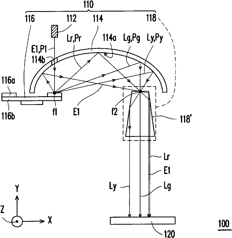
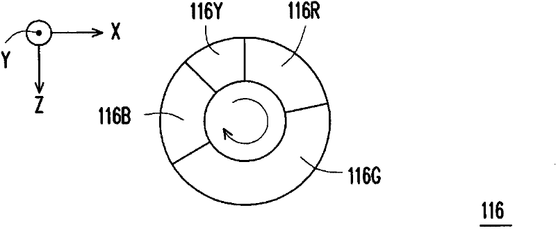
[0022] Figure 1A It is a schematic diagram of the projection apparatus according to the first embodiment of the present invention. Figure 1B for Figure 1A The schematic top view of the wavelength conversion element on the XZ plane. Please refer to Figure 1A , the projection apparatus 100 of this embodiment includes a light source module 110 and a light valve 120 . The light source module 110 includes a light emitting element 112 , a reflection element 114 , a wavelength conversion element 116 and an optical element 118 . The light-emitting element 112 emits an excitation light beam E1 (excitation light). In this embodiment, the light-emitting element 112 is, for example, a blue solid-state laser, an ultraviolet laser (UV laser), or a blue light emitting diode, and the wavelength range of the excitation beam E1 is, for example, in the range of Greater than or equal to 380 nanometers and less than or equal to 460 nanometers. The reflective element 114 includes a reflectiv...

no. 2 example

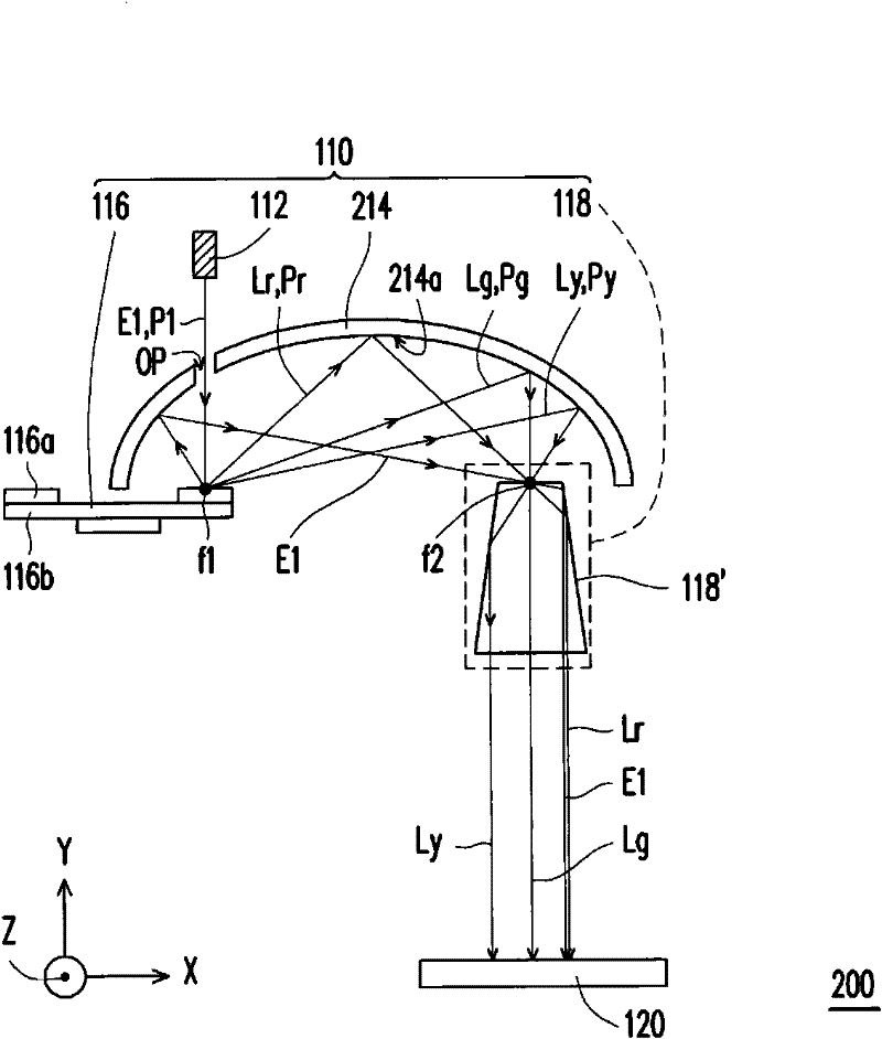
[0029] figure 2 It is a schematic diagram of a projection device according to a second embodiment of the present invention. figure 2 The projection device 200 and Figure 1A Similar to the projection device 100 of the above-mentioned projection device 100, the main difference between the two is that: the reflective element 214 of the projection device 200 also includes an opening OP. The opening OP is located between the light emitting element 112 and the wavelength conversion element 116 , so that the excitation beam E1 passes through the opening OP and is delivered to the wavelength conversion element 116 . Next, the excitation beam E1 is irradiated onto the reflective region 116B of the wavelength converting element 116 (shown in Figure 1B ), it will be reflected from the focal point f1 to the focal point f2 and transmitted to the optical element 118 . In this way, the colored light beams Lr, Lg, Ly and the exciting light beam E1 of different colors can be delivered to...

no. 3 example

[0031] Figure 3A is a schematic diagram of a projection device according to a third embodiment of the present invention. Figure 3B for Figure 3A The schematic top view of the wavelength conversion element on the XZ plane. Please refer to Figure 3A , the projection device 300 of this embodiment includes a light source module 310 and a light valve 120 . The light source module 310 includes a light emitting element 112 , a reflective element 314 , a wavelength converting element 316 and an optical element 318 . The projection device 300 of this embodiment and Figure 1A The projection device 100 is similar to the above-mentioned projection device 100, and the main difference between the two is that the optical element 318 of this embodiment is a color separation unit 318', wherein the color separation unit 318' is arranged between the light emitting element 112 and the reflection element 314 and near the focal point f2 and On the transmission paths Pr, Pg, Py of the color...


PUM


Abstract

The invention relates to a light source comprising a light emitting element, a reflecting element, a wavelength converting element and an optical element, wherein the light emitting element emits an excitation beam; the reflecting element comprises a reflection surface with a first focal point and a second focal point; the wavelength converting element comprises a plurality of excitation areas and is arranged close to the first focal point and on a transmission path of the excitation beam; depending on the rotation of the wavelength converting element, the excitation beam irradiates on different multiple excitation areas at different time so that the excitation beam is converted into a plurality of wavelength beams at the different time; the wavelength beams respectively correspond to the excitation areas, are reflected by the reflection surface and are converged into the second focal point; and the optical element is arranged close to the second focal point and on the transmission path of the wavelength beam, thus the wavelength beam is transmitted to the optical element through the second focal point.

Description

technical field [0001] The present invention relates to a light source module and a projection device, and in particular to a high-brightness light source module and a projection device. Background technique [0002] With the advancement of display technology, in addition to using a high-pressure mercury lamp (UHP lamp) that emits white light, the projection device can use a color wheel to sequentially generate red light, green light and blue light, so that the projection device can provide In addition to color image screens, projection devices using red, green and blue light emitting diodes (LEDs) as light sources have recently been developed. [0003] In a projection device using light emitting diodes as light sources, the light beams emitted by the red, green and blue light emitting diodes are combined by a light combining system, so that light beams of different colors in different transmission directions can be guided to the same direction. Since the brightness of the ...

Claims


Application Information

Patent Timeline
Patent Type & Authority Applications(China)
IPC IPC(8): G03B21/20G02B27/10G02B27/09G02B27/18G03B21/00F21V13/00
CPCG02B19/0028G02B26/008G02B27/0994G02B27/1053G03B21/204
Inventor 杨子宜戴晟杰陈科顺王嘉豪
Owner CORETRONIC
Learn More