50-ampere power consumption balanced-type high-power constant-current source

A high-power, constant-current source technology, applied in emergency protection circuit devices, instruments, control/regulation systems for limiting overcurrent/overvoltage, etc., can solve the problem of short service life of power devices, insufficient maximum output current, Problems such as large power loss, to achieve the effect of reducing the number of components and reducing the design cost

Inactive Publication Date: 2012-08-15
JILIN UNIV
View PDF6 Cites 6 Cited by
  • Summary
  • Abstract
  • Description
  • Claims
  • Application Information

AI Technical Summary

Problems solved by technology

[0004] In order to overcome the shortcomings of the existing high-power constant current sources such as insufficient maximum output current, short service life of power devices, and low system reliability due to large power loss, the present invention provides a desktop constant current source for driving high-power loads. Flow source instrument, the high-pow

Method used


Image

  • 50-ampere power consumption balanced-type high-power constant-current source
  • 50-ampere power consumption balanced-type high-power constant-current source
  • 50-ampere power consumption balanced-type high-power constant-current source

Examples


Embodiment 1

[0026] Embodiment 1 illustrates the overall structure of the present invention with reference to the drawings

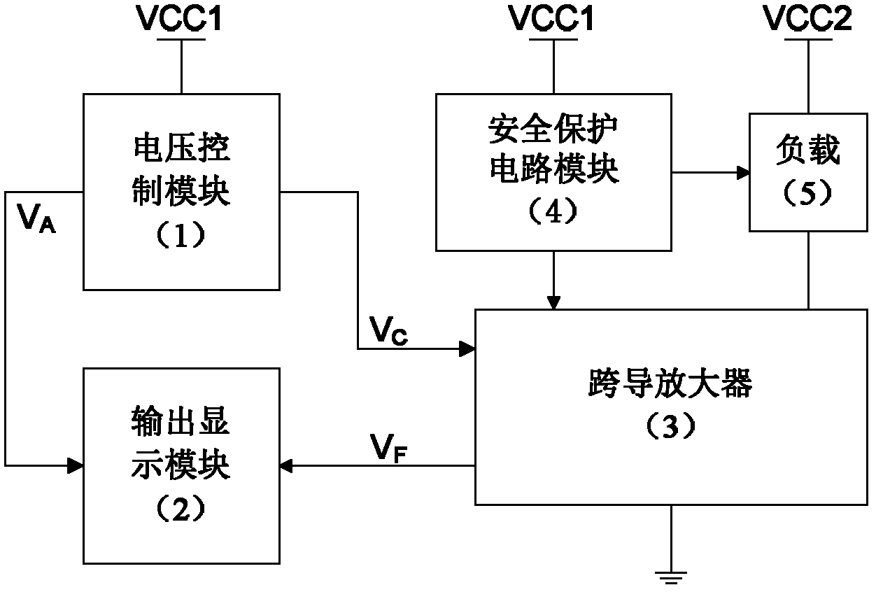
[0027] The power consumption balance type high-power constant current source of the present invention has the structure: voltage control module 1, output display module 2, transconductance amplifier 3, safety protection circuit module 4, and the structure block diagram is as follows figure 1 As shown, the output port V of the voltage control module 1 C Connected to the transconductance amplifier 3, the transconductance amplifier 3 generates the required constant current signal to drive the load 5. The safety protection circuit module 4 provides safety protection to the load. At the same time, the output port V of the voltage control module 1 A And output port V of transconductance amplifier module 3 F Connected to the mode selection input terminal of the output display module 2, the output display module 2 displays the current limit value and the actual current value.

Embodiment 2

[0028] Embodiment 2 Voltage Control Module 1

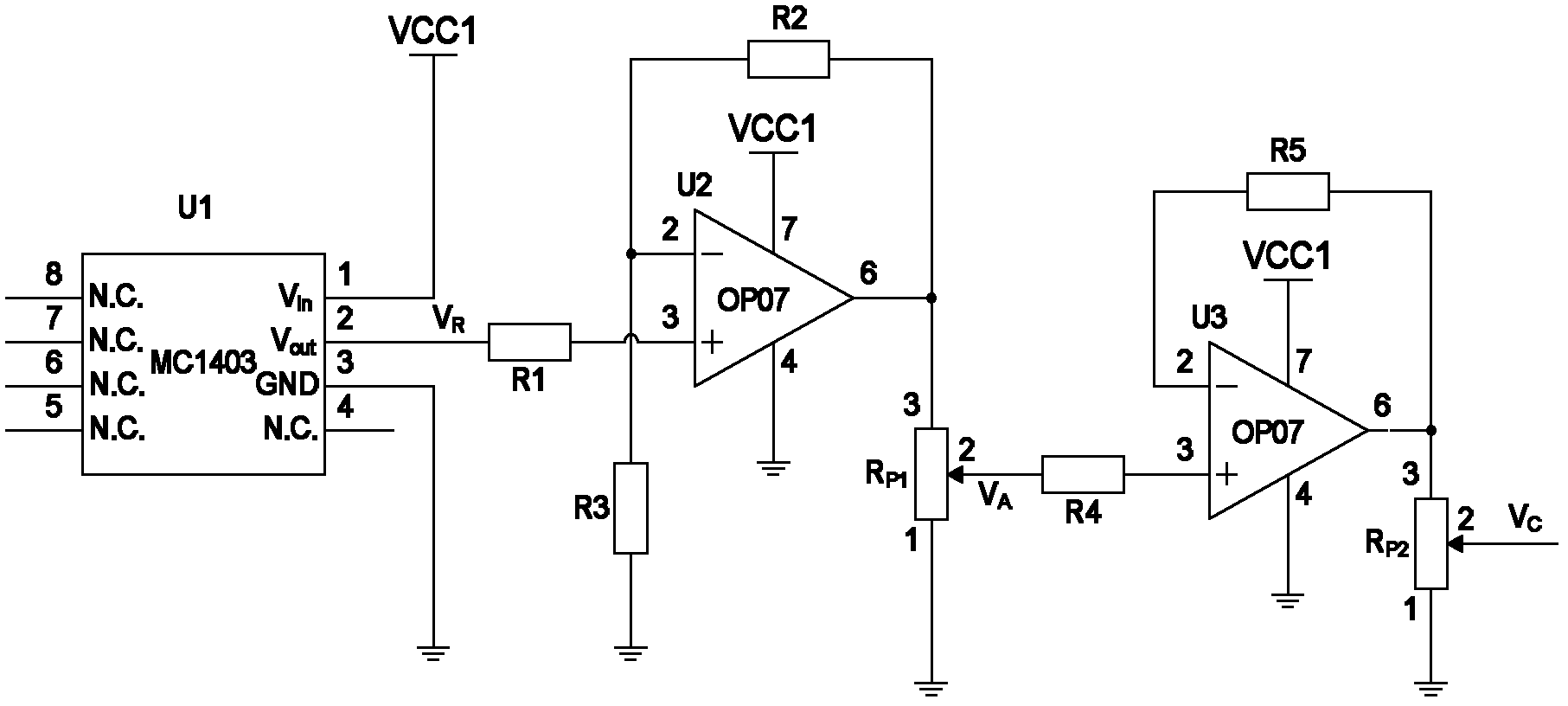
[0029] Such as figure 2 As shown, the voltage control module 1 includes: 1 pin of the voltage reference chip U1 (MC1403) is connected to the power supply VCC1 (+15V, rated power 30W), the 3 pin is grounded, and the 2 pin is connected to the single operational amplifier U2 (OP07) through the resistor R1 (15kΩ) ), pin 4 of single op amp U2 (OP07) is grounded, pin 7 is connected to power supply VCC1 (+15V, rated power 30W), pin 2 is grounded through resistor R3 (30kΩ), pin 2 of single op amp U2 (OP07) The pin is connected to the 6 pin of the single op amp U2 (OP07) through the resistance R2 (30kΩ), and the 6 pin of the single op amp U2 (OP07) is connected to the potentiometer R p1 (100kΩ) 3 feet, potentiometer R p1 (100kΩ) pin 1 is grounded, pin 2 is connected to the output port V of the voltage control module 1 A , Output port V A Connect to the mode selection input terminal of the output display module 2, and the potentiometer R p1 (1...

Embodiment 3

[0030] Embodiment 3 Transconductance amplifier 3

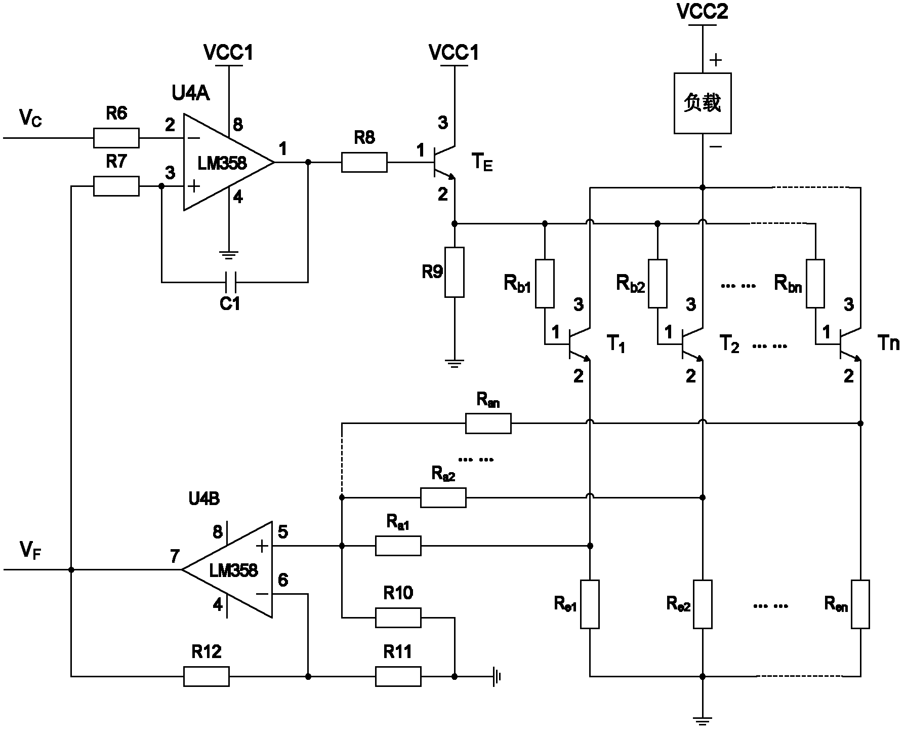
[0031] Such as image 3 As shown, the transconductance amplifier 3 includes: 4 pins of the dual operational amplifier U4A (LM358) are grounded, 8 pins are connected to the power supply VCC1 (+15V, rated power 30W), and 2 pins are connected to the output of the voltage control module 1 through a resistor R6 (10kΩ) Port V C , Connected to the control signal output port of the soft-start protection circuit in the safety protection circuit module 4, pin 3 is connected to the output port V of the transconductance amplifier 3 through the resistor R7 (10kΩ) F At the same time, pin 3 of dual op amp U4A (LM358) is connected to pin 1 of dual op amp U4A (LM358) through capacitor C1 (4.7μF), pin 1 of dual op amp U4A (LM358) is connected to type N through resistor R8 (1kΩ) Darlington Power Transistor T E (TIP132) 1 pin, N-type Darlington power transistor T E (TIP132) pin 3 is connected to the power supply VCC1 (+15V, rated power 30W), pin 2 is...


PUM

PropertyMeasurementUnit
Capacitanceaaaaaaaaaa
Resistanceaaaaaaaaaa

Abstract

The invention discloses a 50-ampere power consumption balanced-type high-power constant-current source and belongs to the technical field of electronic equipment. The constant-current source is structurally characterized in that a voltage control module (1) generates continuous adjustable voltage signals VC for controlling a transconductance amplifier (3), the transconductance amplifier (3) generates a constant current signal for driving a load (5), a safety protection circuit module (4) provides security protection for the load, and the output port VA of the voltage control module (1) and the output port VF of the transconductance amplifier module (3) are connected to the mode selecting input end of an output display module (2). The invention provides a constant-current source for driving a high-power semiconductor laser array, and the maximum output current of the constant-current source can be up to 50 amperes; and the constant-current source is of a power consumption balanced-type structure, so that the power loss and heat are uniformly dispersed and timely discharged and then not accumulated, and the redundancy of a constant-current driver is enhanced, thereby improving the stability, reliability and maximum output current of the high-power constant-current source.

Description

Technical field [0001] The invention belongs to the technical field of electronic equipment, and particularly relates to a 50-ampere power consumption balanced high-power constant current source. Background technique [0002] With the continuous increase of electric energy consumption and the high-functionalization of energy utilization forms, high-current technology is a rapidly emerging field in the generation, transmission, transformation and control of electric energy. At the same time, the high-power constant current source, as a branch of the stable power supply, has a very wide range of applications in the power research field. However, in many occasions where a constant current source should be used, a regulated power supply is still inappropriately used. In most cases, a high-precision current source with a large working current still needs to be designed and implemented by the user. Therefore, it is urgent to design a practical high-power constant current source, and p...

Claims


Application Information

Patent Timeline
IPC IPC(8): G05F1/56H02H9/02
Inventor 田小建单江东吴戈汝玉星高博
Owner JILIN UNIV
Why Eureka
Try Eureka