
Packaging and stacking device and method for manufacturing same

A stacking and stacking technology, which is applied in the field of package stacking device and its manufacturing method, can solve problems such as inclined placement, influence on product yield, difficult control of solder ball 110 size variation, etc., and achieve the effect of avoiding warping

Inactive Publication Date: 2012-08-15
UNIMICRON TECH CORP
View PDF11 Cites 21 Cited by
  • Summary
  • Abstract
  • Description
  • Claims
  • Application Information

AI Technical Summary

Problems solved by technology

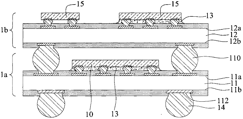
[0005] However, in the existing device, the first package structure 1a and the second package structure 1b are stacked by soldering process, resulting in the solder material of the solder ball 110 easily contaminating the first package structure 1a and the second package structure 1b during the reflow process. The surface of the second packaging structure 1b, and the size variation of the solder ball 110 is not easy to control, so it is easy to cause the two packaging structures to be placed in an oblique connection, resulting in the problem of contact offset
[0006] In addition, when the height of the stack needs to be increased, the diameter of the solder ball 110 needs to be increased, resulting in an increase in the area of ​​the substrate surface (the first surface 11a and the fourth surface 12b) occupied by the solder ball 110, thus increasing the area on the substrate surface. Condensed space for cabling and electronics placement
[0007] Moreover, the volume of the solder ball 110 increases, which is prone to bridging (bridge), which will affect the yield of the product.
[0008] In addition, the first package structure 1a and the second package structure 1b are only supported by the solder balls 110, because there is too much space between the first package structure 1a and the second package structure 1b, resulting in the first package structure 1a and the second package structure 1b. One and the second substrate 11, 12 are prone to warping (warpage)

Method used


Image

  • Packaging and stacking device and method for manufacturing same
  • Packaging and stacking device and method for manufacturing same
  • Packaging and stacking device and method for manufacturing same

Examples


Embodiment Construction

[0060] The implementation of the present invention will be described below through specific examples, and those skilled in the art can easily understand other advantages and effects of the present invention from the content disclosed in this specification.

[0061] see Figure 2A to Figure 2G , which is a schematic cross-sectional view of the first embodiment of the manufacturing method of the package stacking device of the present invention.

[0062] Such as Figure 2A As shown, firstly, a first substrate 21 having opposite first surface 21a and second surface 21b is provided, on the first surface 21a of the first substrate 21 there are a plurality of welding pads 211a and electrical contact pads 211b, and The second surface 21 b of the first substrate 21 has a plurality of ball planting pads 212 .

[0063] In this embodiment, the first and second surfaces 21a, 21b of the first substrate 21 have an insulating protective layer 213 such as a solder resist layer, and the insul...


PUM


Abstract

Disclosed are a packaging and stacking device and a method for manufacturing the same. The packaging and stacking device comprises a first packaging structure, a second packaging structure and packaging adhesive, a first metal column and a first electronic component are arranged on the surface of the first packaging structure, a second metal column and a second electronic component are disposed on the surface of the second packaging structure, the packaging adhesive is arranged between the first packaging structure and the second packaging structure and covers the first electronic component, the second packaging structure is stacked on the first packaging structure by means of connecting the second metal column with the first metal column, accordingly, the two packaging structures are not supported by the metal columns, a gap between the two packaging structures is filled by the packaging adhesive, and a substrate can be prevented from warping.

Description

technical field [0001] The present invention relates to a packaging and stacking device and a manufacturing method thereof, in particular to a packaging and stacking device and a manufacturing method thereof capable of improving the stacking yield. Background technique [0002] With the evolution of semiconductor packaging technology, different packaging types have been developed for semiconductor devices. In order to improve electrical functions and save packaging space, multiple packaging structures are stacked to form a package stack device (Package on Package) , POP), this type of packaging can take advantage of the heterogeneous integration characteristics of the system in package (SiP), and can integrate electronic components with different functions, such as: memory, central processing unit, graphics processor, image application processor, etc., through stack design It achieves system integration and is suitable for various thin and light electronic products. see fi...

Claims


Application Information

Patent Timeline
IPC IPC(8): H01L25/00H01L25/065H01L23/48H01L23/52H01L23/31H01L21/58H01L21/60H01L21/56
CPCH01L24/73H01L2224/16225H01L2224/32225H01L2224/48227H01L2224/73204H01L2224/73265H01L2924/15311H01L2924/15321H01L2924/30107H01L2924/00012H01L2924/00
Inventor 胡迪群
Owner UNIMICRON TECH CORP
Learn More