APF (Active Power Filter)parallel system and control method thereof
A control method and parallel technology, applied in active power filtering, AC network to reduce harmonic/ripple, reactive power adjustment/elimination/compensation, etc., can solve system design difficulties, reduce and increase control delay To achieve high reactive power compensation accuracy and harmonic suppression capability, suppress system circulation, and avoid voltage fluctuations
- Summary
- Abstract
- Description
- Claims
- Application Information
AI Technical Summary
Problems solved by technology
Method used
Image

Examples
Embodiment Construction
[0048] In order to describe the present invention more specifically, the APF parallel system and its control method of the present invention will be described in detail below in conjunction with the accompanying drawings and specific embodiments.
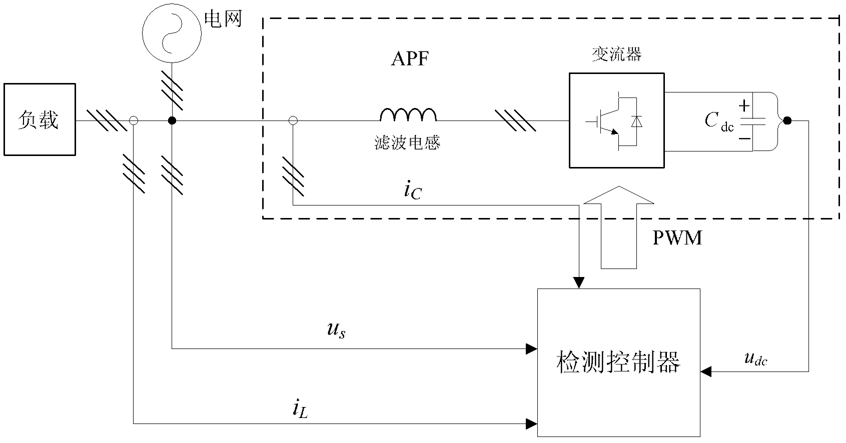
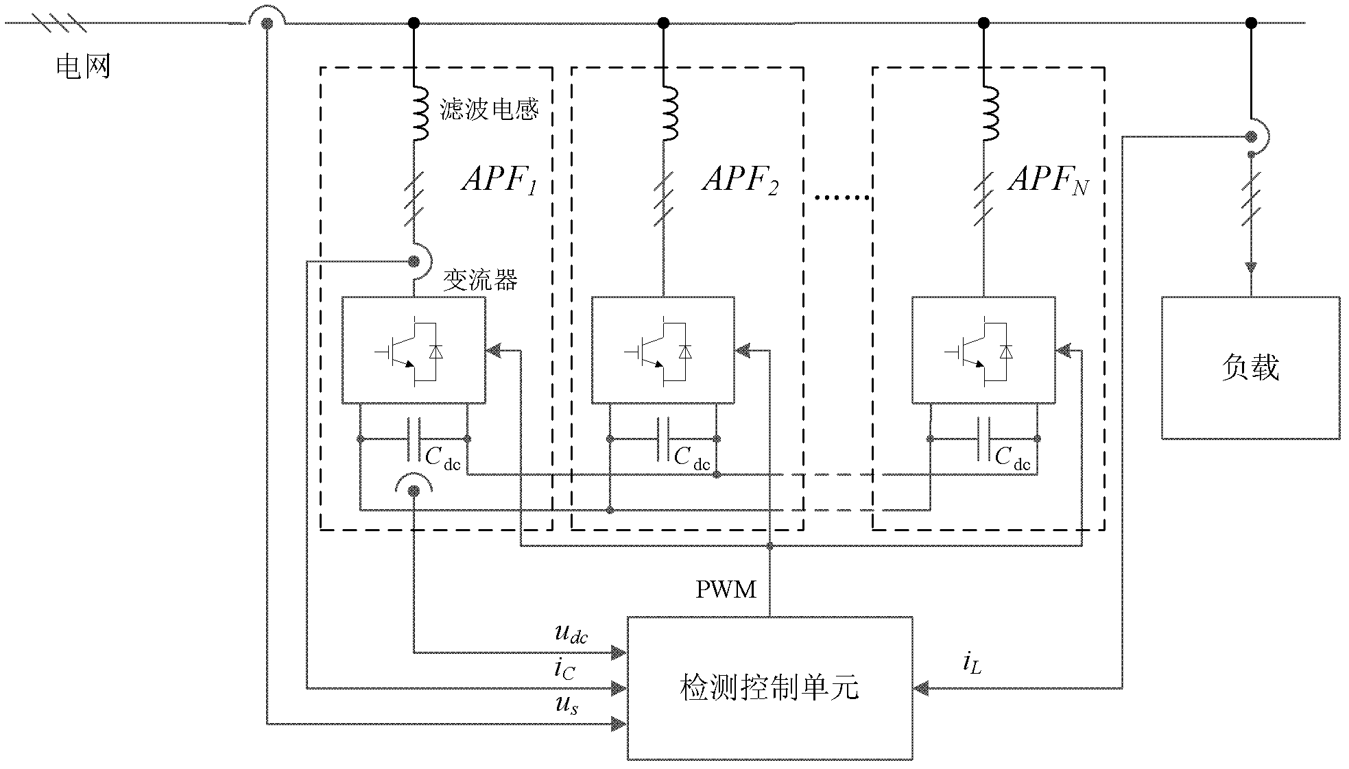
[0049] Such as figure 2 As shown, an APF parallel system includes N APFs connected to the power grid and a detection control unit;
[0050] APF is used to inject compensation current into the grid; it consists of a converter and a filter inductor; the grid side of the converter is connected to the grid through a filter inductor, and the DC side is connected in parallel with a DC support capacitor C dc ; The high-voltage terminals of all APF DC support capacitors are connected together, and the low-voltage terminals of all APF DC support capacitors are connected together. The converter is a three-phase half-bridge structure, and each bridge arm is composed of multiple IGBTs connected in parallel.
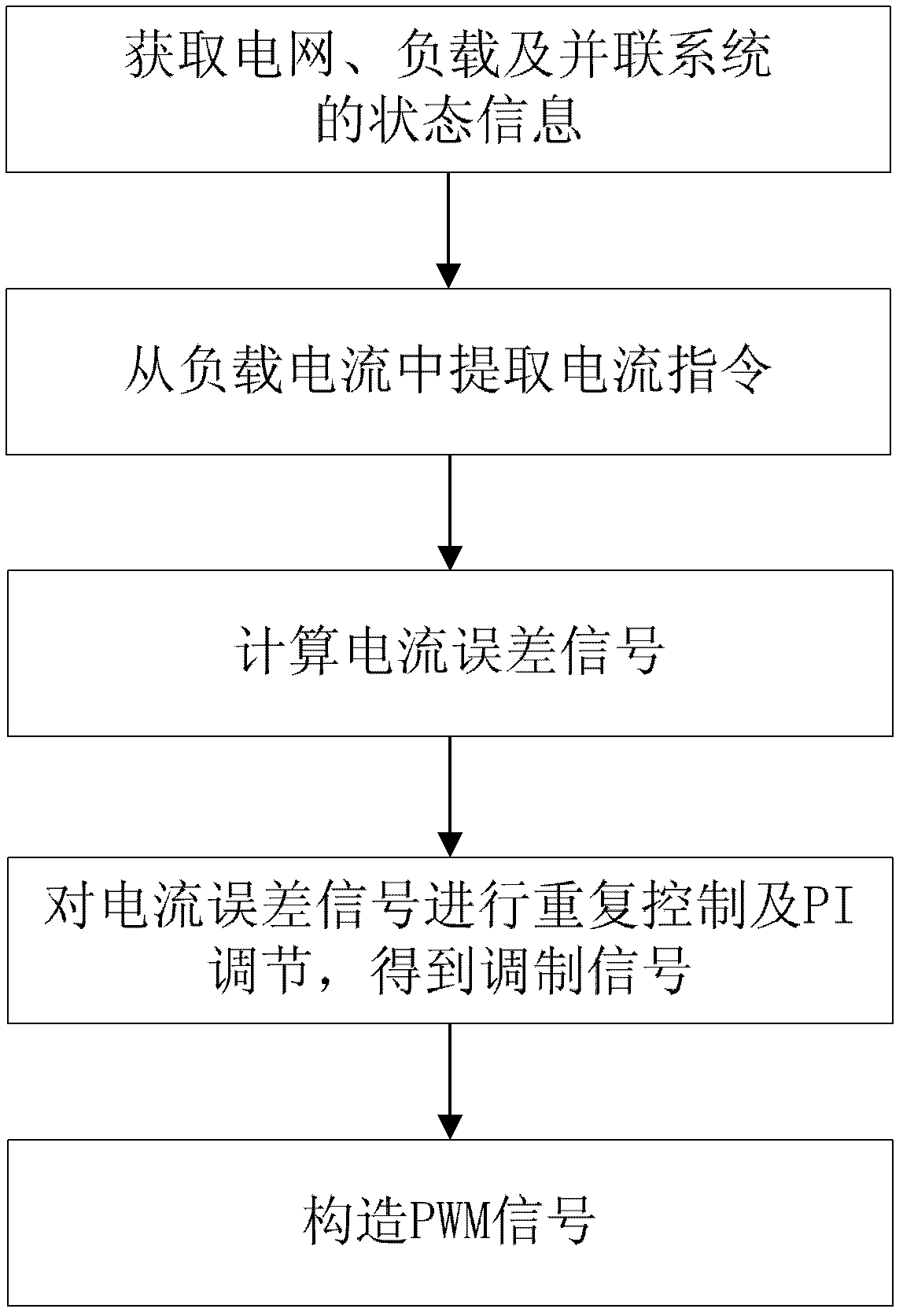
[0051] The detection control unit...
PUM
 Abstract
Description
Claims
Application Information