Orifice piece and atomization assembly with same

A technology of atomizing components and orifice sheets, which is applied in the field of atomizers, and can solve problems such as shortened service life, collision of liquid droplets together, and large amplitude in the central area of ​​the orifice sheet 112.

Inactive Publication Date: 2012-08-22
MICRO BASE TECH CORP
View PDF8 Cites 6 Cited by
  • Summary
  • Abstract
  • Description
  • Claims
  • Application Information

AI Technical Summary

Problems solved by technology

[0005] 1. When the piezoelectric ring 113 vibrates, the transmission direction of the vibration wave generated is from the outer edge of the orifice plate 112 to the center, resulting in excessive concentration of vibration energy at the center of the orifice plate 112 , causing the central area of ​​the orifice plate 112 to have too large a vibration amplitude, which is easily broken due to stress concentration, and thus shortens the service life
[0006] 2. Since the vibration energy is concentrated at the center of the orifice plate 112, the atomization area can only be formed near the center of the orifice plate 112
Because the atomization area is only formed at the center of the orifice plate 112, the effective use of the multiple percussion holes 1121 on the orifice plate 112 is reduced, and the amount of atomization is not good
[0007] 3. During the atomization process, the liquid and gas must be exchanged to maintain the balance of the internal and external pressure difference of the atomization device. Because the atomization area is too small, the spray state is unstable, and the spray volume is easy to fluctuate.
[0008] 4. Due to the excessive concentration of the spray area in the central area, the density of the atomized liquid molecules is excessively concentrated, and it is easy to make the droplets collide together, and combine to form large-sized droplets, resulting in a decrease in the atomization efficiency
However, the effective atomization range will be reduced
If you want to increase the effective atomization range, you must incr...

Method used


Image

  • Orifice piece and atomization assembly with same
  • Orifice piece and atomization assembly with same
  • Orifice piece and atomization assembly with same

Examples


Embodiment Construction

[0063] In order to enable your examiner to clearly understand the content of the present invention, the following descriptions are provided together with the accompanying drawings, please refer to them.

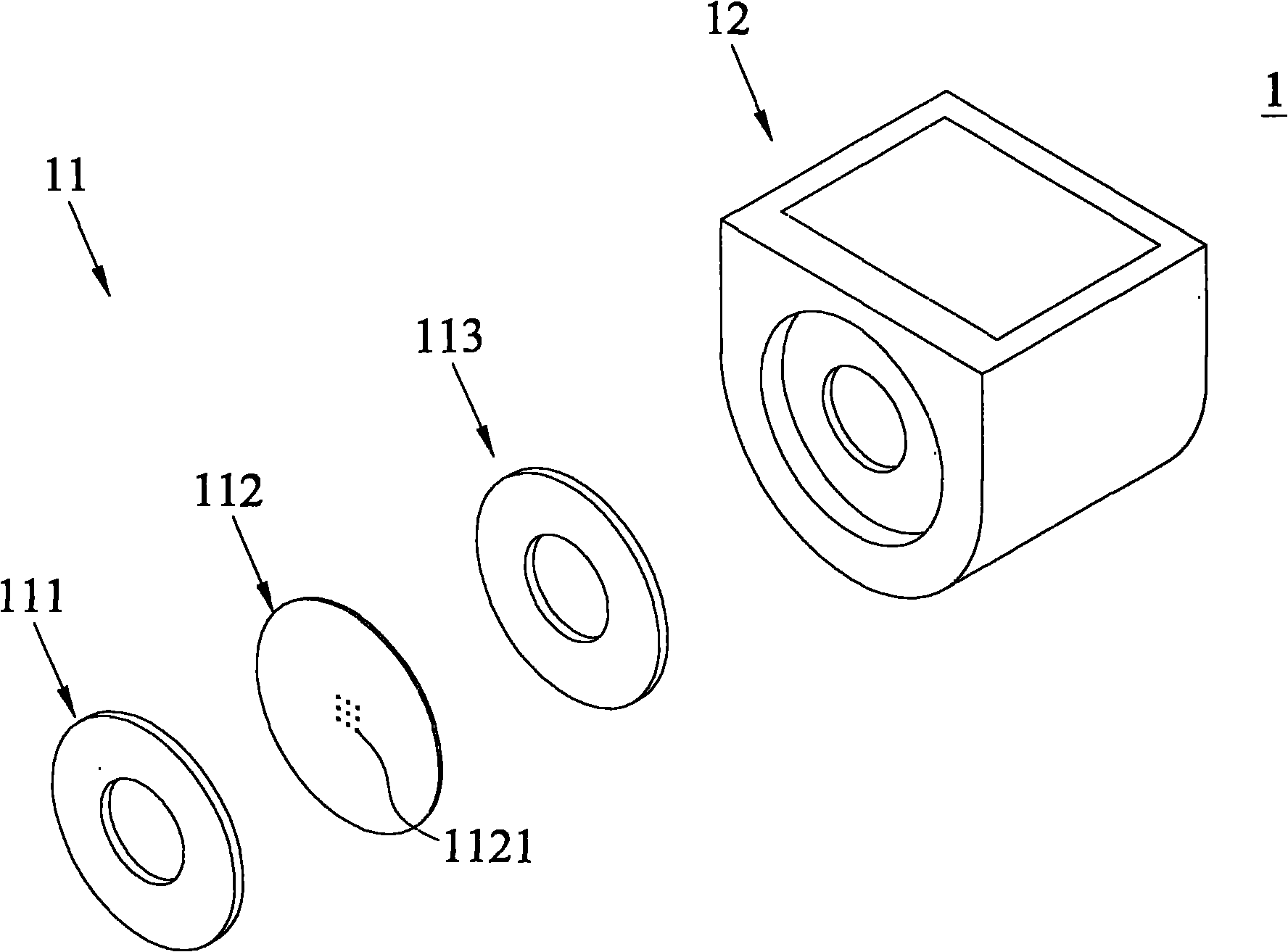
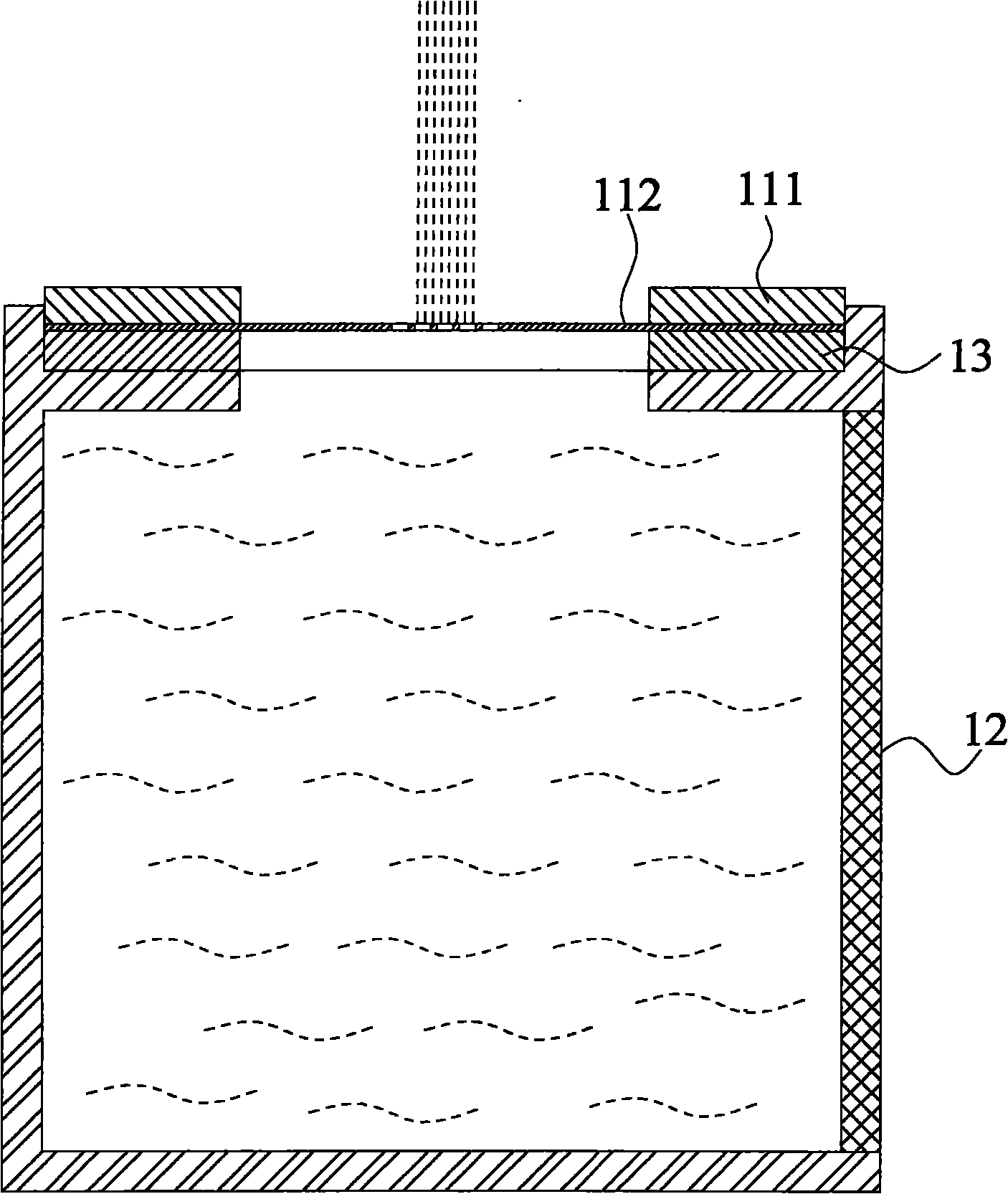
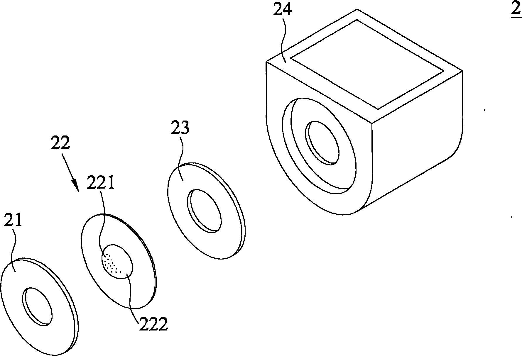
[0064] see Figure 7A , Figure 7B , Figure 8 and Figure 9 As shown, it is an exploded view, a schematic diagram of the nozzle hole sheet, a cross-sectional view and a schematic diagram of the nozzle hole sheet of the first embodiment of the nozzle hole sheet of the present invention and the atomization assembly using it. In the figure, the atomization assembly 3 is disposed on one side of a cavity 34 and includes a piezoelectric ring 31 , an orifice 32 and a braking ring 33 .

[0065] The piezoelectric ring 31 can be made of piezoelectric ceramics made of lead zirconate titanate material, and has an outer diameter 311 and an inner diameter 312 .

[0066] The brake ring 33 is a metal ring with an outer diameter 331 and an inner diameter 332 , and is disposed on one side...


PUM


Abstract

The invention discloses an orifice piece and an atomization assembly with the same. The atomization membrane assembly is arranged on a cavity and comprises a piezoelectric ring piece, a brake ring piece and the orifice piece, wherein the brake ring piece is arranged on one side of the piezoelectric ring piece; the orifice piece is disc-shaped, clamped between the piezoelectric ring piece and the brake ring piece and provided with a plurality of triggering holes and first upheaval parts; and the plurality of first upheaval parts are non-circular and protrude and stretch convexly towards the direction of the piezoelectric ring piece or the brake ring piece to form a multi-curve structure arranged in a radiation or ring shape with a specific geometric modeling pattern. Therefore, the orifice piece can be used for enlarging the atomization region and improving the atomization quantity and the liquid-gas exchange efficiency, and can be prevented from being cracked since stress is excessively concentrated at the center of the orifice piece during vibration.

Description

technical field [0001] The invention belongs to the field of atomizers, and particularly relates to an orifice sheet with a radial or circular arrangement of geometric patterns in the center of the orifice sheet and an atomization assembly using the multi-curved surface structure. Background technique [0002] The atomizer, such as the common ultrasonic atomizer, is mainly composed of piezoelectric (PZT) ceramics made of lead zirconate titanate. After a voltage is input, the ceramic body and the attached metal back plate will undergo telescopic deformation. The energy is transmitted in the form of waves, making it work at the frequency of ultrasonic waves, and its amplitude is in the range of microns, which is controlled by the input voltage. The vibration generated by the piezoelectric material is used to transmit the ultrasonic wave to the orifice sheet, so that the liquid near the orifice is subjected to the Rayleigh Wave (Rayleigh Wave) or surface wave, and the liquid is...

Claims


Application Information

Patent Timeline
IPC IPC(8): B05B17/04
Inventor 谢淑品苏玉如黄家桢林建华许由忠林泰轩黄美惠熊介铭
Owner MICRO BASE TECH CORP
Why Eureka
Try Eureka