Novel power transmission mechanism of all-hydraulic drill

A power transmission mechanism and full hydraulic technology, applied in rotary drilling rigs, mechanical equipment, earthwork drilling and mining, etc., can solve the problems of reducing the overall volume of the gearbox, occupying a large space and weight, heat and wear, etc. The conversion is convenient and reliable, the sealing performance is good, and the effect of reducing loss

Inactive Publication Date: 2012-08-22
HENGYANG ZHONGDI EQUIP PROSPECTING ENG MACHINERY
View PDF5 Cites 8 Cited by
  • Summary
  • Abstract
  • Description
  • Claims
  • Application Information

AI Technical Summary

Problems solved by technology

[0005] 1. The axis of the speed change shaft in the gearbox is parallel to the axis of the drill pipe, and when the drilling rig is working, the drill pipe is basically perpendicular to the ground, which requires the shift fork in the gearbox not only to change gears, but also to Bearing most of the weight of the shift gear, the frictional motion between the shift gear and the shift fork as the gear rotates creates a lot of heat and wear, and can easily cause skipped gears
[0006] 2. Because the power head occupies a certain space, a certain distance must be guaranteed between the gearbox and the drill pipe, and the length direction of the gearbox and the length direction of the gearbox must be placed at an angle of approximately 90°, otherwise, the gearbox and the drill pipe must be placed at an angle of approximately 90°. The distance between the rods will be too large; in the case of a compact structure, a transition gear and a transition shaft must be added in the middle of the gearbox to ensure that the outer diameter of the first-stage gear is as small as possible, thereby reducing the overall volume of the gearbox ; Even so, the occupied space and weight of the whole set of power transmission mechanism are still relatively large, which also causes waste of power and waste of materials;
[0007] 3. In the working state, in the whole set of power transmission mechanism, there are many bearings facing downwards, which brings a certain degree of difficulty to the sealing, and oil leakage occurs from time to time

Method used


Image

  • Novel power transmission mechanism of all-hydraulic drill
  • Novel power transmission mechanism of all-hydraulic drill
  • Novel power transmission mechanism of all-hydraulic drill

Examples


Embodiment Construction

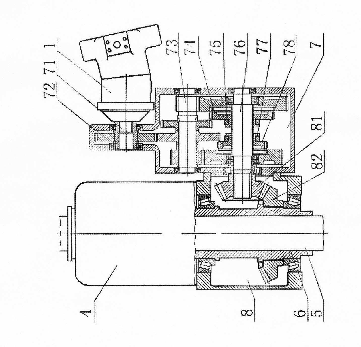
[0022] like image 3 , 4 Shown: a new type of full hydraulic drilling rig power transmission mechanism, including hydraulic motor 1, gearbox 7, gearbox 8, power head 4, drill pipe 5 and drill pipe sleeve 6, hydraulic motor 1 is located on gearbox 7, gearbox 7 includes starting gear shaft 71, starting gear 72, active shifting shaft 73, right shifting gear 74, right shifting fork 75, passive shifting shaft 76, left shifting fork 77 and left shifting gear 78. Gear shaft 71, active transmission shaft 73 and passive transmission shaft 76 are all installed in the gearbox 7, and their axes are all perpendicular to the axis of drill rod 5, and starting gear 72 is installed on the starting gear shaft 71, and is connected with driving transmission shaft 73 The gears on the gear mesh, the right shift gear 74 and the left shift gear 78 are installed on the passive shift shaft 76, the right shift fork 75 and the left shift fork 77 are respectively located on the right shift gear 74 and th...


PUM


Abstract

A novel power transmission mechanism of an all-hydraulic drill comprises a hydraulic motor 1, a speed changing box 7, a gear box 8, a power head 4, a drill rod 5 and a drill rod sleeve 6. A starting gear shaft 71, a starting gear 72, a driving speed changing shaft 73, a right shifting gear 74, a right shifting fork 75, a driven speed changing shaft 76, a left shifting fork 77 and a left shifting gear 78 are arranged in the speed changing box 7. Axes of the starting gear shaft 71, the driving speed changing shaft 73 and the driven speed changing shaft 76 are all perpendicular to an axis of the drill rod 5, the gear box 8 is integrated with the power head 4, located below the power head 4 and connected with the speed changing box 7, a small bevel gear 81 is installed on the driven speed changing shaft 76 extending in the gear box 8, a large bevel gear 82 is installed on the drill rod sleeve 6 and meshed with the small bevel gear 81, and the drill rod 5 is installed in the power head 4 through the drill rod sleeve 6. Compared with the prior art, the novel power transmission mechanism of the all-hydraulic drill has the advantages of being convenient and reliable in gear change, compact in structure, high in transmission efficiency, good in sealing performance and the like.

Description

technical field [0001] The invention relates to a drilling rig equipment used in the geological drilling industry, in particular to a novel full hydraulic drilling rig power transmission mechanism. Background technique [0002] In the field of drilling industry, the full hydraulic drilling rig has become a development trend of drilling equipment due to its advantages of simple operation, flexible displacement, accurate and reliable drilling positioning, high work efficiency and good safety. [0003] The structure of the most commonly used power transmission mechanism of a fully hydraulic drilling rig is as follows: figure 1 , 2 As shown, it includes a hydraulic motor 1, a gearbox 2, a gearbox 3, a power head 4, a drill pipe 5 and a drill pipe sleeve 6, the hydraulic motor 1 is located on a gearbox 2, and the gearbox 2 includes an active transmission shaft 21, The upper shift gear 22, the upper shift fork 23, the lower shift fork 24, the lower shift gear 25 and the passive ...

Claims


Application Information

Patent Timeline
Patent Type & Authority Applications(China)
IPC IPC(8): F16H3/087F16H57/023E21B3/02
Inventor 欧阳志强卢春阳柴喜元李文汪石山
Owner HENGYANG ZHONGDI EQUIP PROSPECTING ENG MACHINERY
Why Eureka
Try Eureka