Grooving spiral curling rotor in heat exchange tube

A heat exchange tube and spiral coil technology, which is applied in the field of slotted spiral coil rotors, can solve the problems of enhanced heat transfer and anti-scaling and descaling capability, reduced heat transfer performance, and reduced service life, etc. ability, the ability to improve heat transfer enhancement, the effect of reducing the possibility of deposition

Inactive Publication Date: 2012-08-22
BEIJING UNIV OF CHEM TECH
View PDF7 Cites 9 Cited by
  • Summary
  • Abstract
  • Description
  • Claims
  • Application Information

AI Technical Summary

Problems solved by technology

There is generally layered dirt on the inner wall of the shell and tube heat exchanger, which leads to an increase in the resistance of the fluid in the pipeline. In severe cases, the pipeline will be blocked, and the heat transfer performance will be greatly reduced; Energy is wasted. At the same time, the dirt is generally corrosive, and the pipe wall will be corroded. If the fluid leaks, it will cause a major safety hazard. Therefore, the traditional treatment method is to be forced to stop production for cleaning, which not only delays the production progress of the factory, but also Need to pay expensive cleaning fees; in order to better solve these problems, people have been studying various methods and devices for non-stop online automatic heat transfer enhancement and descaling and anti-scaling
The insert, as a typical tube-side enhanced heat transfer method, has also attracted people's attention. Chinese patent application number 201110050891.8, the invention name is "radial stepped rotor in heat exchange tube", the device is composed of rotor, The supporting frame is composed of a connecting axis, the supporting frame is fixed at both ends of the heat transfer tube, the two ends of the connecting axis are respectively fixed on the supporting frame, and a plurality of rotors are mounted on the connecting axis, the rotor is composed of a hollow shaft and blades, and the blades are Stepped shape, each blade and the hollow shaft are in the same inclined shape, adjacent blades are connected end to end, the fluid passing performance is good, but the structure has a relatively large resistance to the fluid, the flow rate is too high, and the axial force of the rotor is superimposed on the pendant and The force of the axis is large, and the life of the shaft will be reduced. The arrangement of the rotor blades described above is evenly distributed on the hollow shaft. In order to facilitate the installation of the rotor, there is a large distance between the outer diameter surface of the rotor and the inner diameter surface of the heat exchange tube. , so the enhanced heat transfer and anti-scaling and descaling capabilities of the rotor are limited to a certain extent.
In addition, the rotor will shake during the rotation process, and the top of the blade will scratch the inner wall of the heat exchange tube, which will also reduce its service life. Therefore, the rotor should have a better centering effect in the heat exchange tube to reduce its friction. The scraping effect with the inner wall of the heat exchange tube prolongs its service life

Method used


Image

  • Grooving spiral curling rotor in heat exchange tube
  • Grooving spiral curling rotor in heat exchange tube
  • Grooving spiral curling rotor in heat exchange tube

Examples


Embodiment Construction

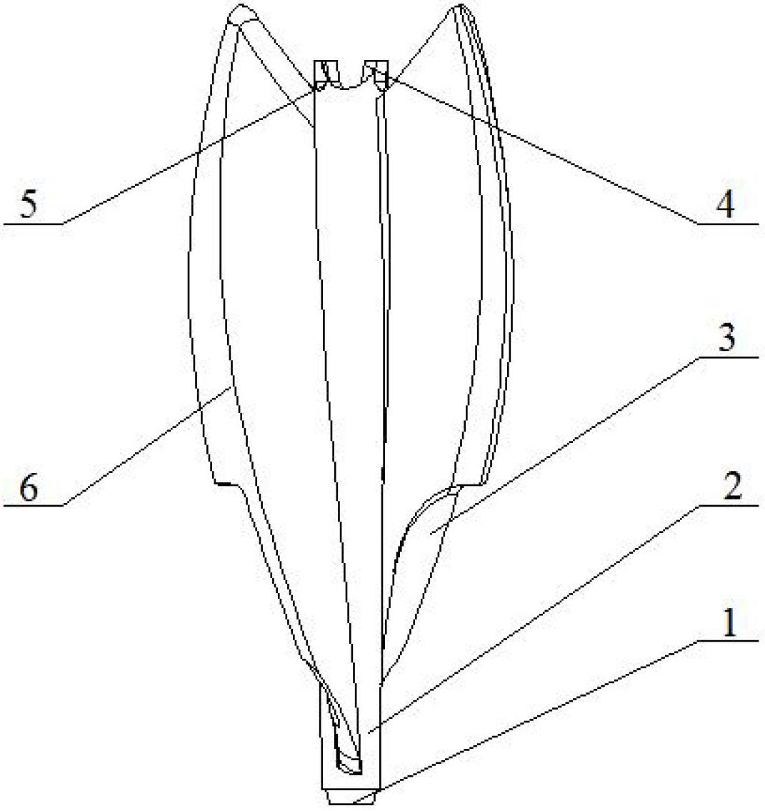
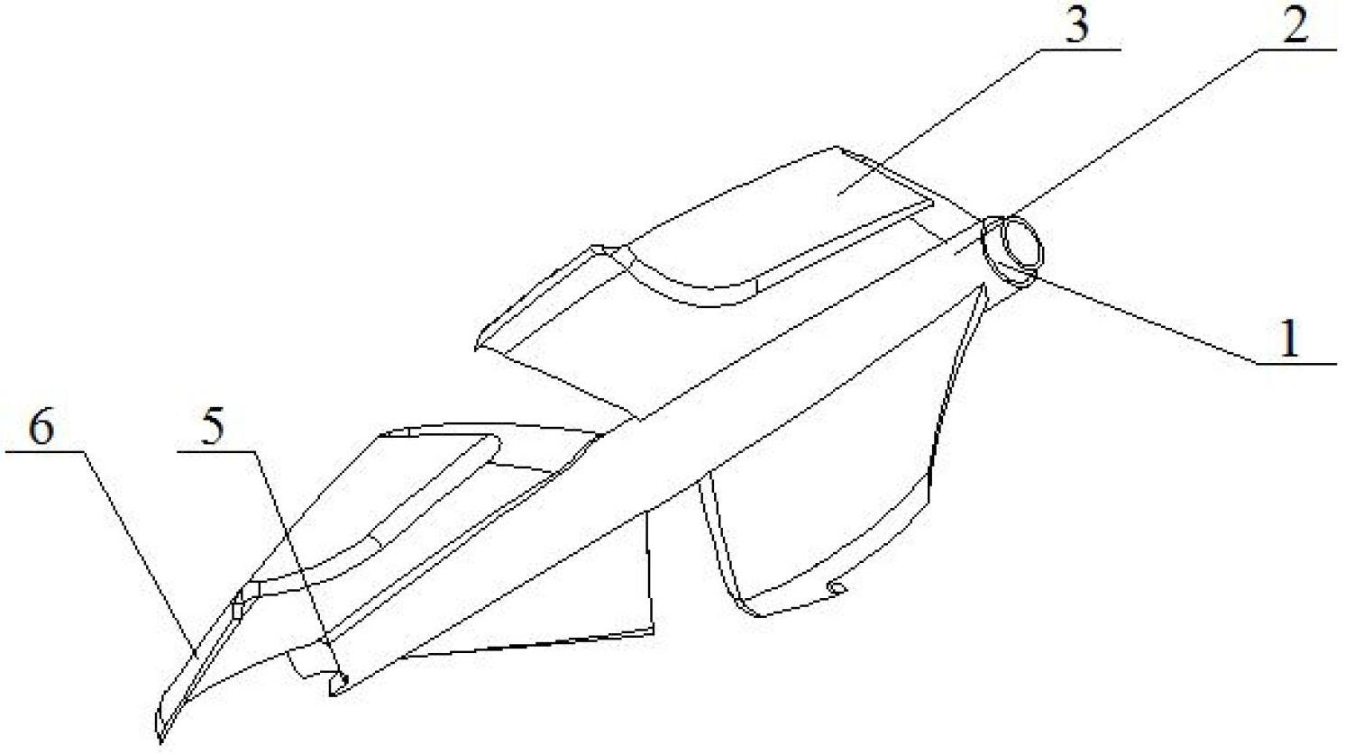
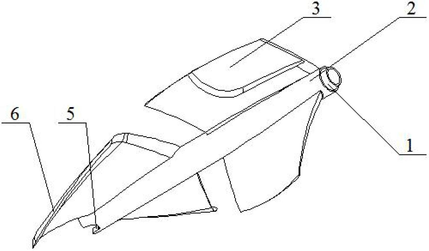
[0025] like Figure 7 As shown, the present invention relates to an implementation method of a slotted spiral crimping rotor in a heat exchange tube. The enhanced heat transfer device includes a rotor, a heat exchange tube 7, a pendant 8 and a rotating shaft 9. Several rotors are connected in series through the rotating shaft 9. Together, the hanger 8 is fixed on both ends of the heat exchange tube 7, and the two ends of the rotating shaft 9 are respectively fixed on the hanger 8. The rotor of the present invention is fixed on the surface of the hollow shaft 2 by a certain number of slotted blades 3 and curled blades 6. Composed, the hollow shaft 2 is also provided with a ball socket boss 1, a ball socket concave table 4 and a hole 5 communicating with the inner hole of the hollow shaft. Among the two adjacent rotors, the ball-socket boss 1 at the head of the hollow shaft 2 of one rotor is combined with the ball-socket recess 4 at the tail of the other rotor to connect and adj...


PUM


Abstract

The invention relates to a grooving spiral curling rotor in a heat exchange tube. The rotor is composed of a hollow shaft and a blade, wherein the hollow shaft is of a tubular structure; the blade is located on the outer surface of the hollow shaft; the blade surface is smooth and spiral around the hollow shaft; the blade of the rotor is composed of a grooving blade and a curling blade; a water-facing surface of the grooving blade is provided with a diversion trench structure along the radial direction of the hollow shaft; the radial thickness of the grooving blade is reduced; a water-back surface is not provided with a diversion trench structure; the edge of the grooving blade in contact with the fluid first is subjected to beveling or rounding; and a curling structure is arranged at the top end of the curling blade and is in transition connection through a smooth curved surface. In the invention, when the grooving blade rotates, the heat transfer fluid generates centrifugal movement along the surface of the diversion trench and is thrown to the wall of the heat exchange tube; a curling structure is arranged at the top end of the curling blade; and the rotor can realize a good self-centering effect when rotating in the fluid according to the self-suspension mechanism of the curling blade so as to reduce the scraping effect between the top end of the blade and the inner wall of the heat exchange tube and increase the fluid turbulence degree.

Description

technical field [0001] The invention relates to an insert device applied to the energy-saving technology of a shell-and-tube heat exchanger, in particular to a slotted spiral crimping rotor with low energy consumption, high efficiency and long service life with self-cleaning and enhanced heat exchange functions. Background technique [0002] In my country, 70% of energy consumption is industrial consumption, and most of the energy consumed by these industries is thermal energy, which is basically realized through the heat exchange process. Typical heat exchange equipment such as condensers of steam turbines in power plants, evaporators in caustic soda and soda ash production units, and ethylene cracking furnaces generally suffer from high energy consumption, low heat exchange efficiency, easy fouling and fouling, frequent cleaning, and waste liquid cleaning The problem of large emissions. The national policy of "energy saving and emission reduction" has effectively promoted...

Claims


Application Information

Patent Timeline
Patent Type & Authority Applications(China)
IPC IPC(8): F28F13/12F28G3/00
Inventor 阎华张震关昌峰丁玉梅杨卫民
Owner BEIJING UNIV OF CHEM TECH
Why Eureka
Try Eureka