Positive temperature coefficient (PTC) electric heater for electric automobile air-conditioning system
A technology for electric heaters and electric vehicles, applied in ohmic resistance heating parts, heating elements, heating/cooling equipment, etc., can solve the problems of inability to meet environmental protection requirements, complicated processes, and the adhesive is not easy to disassemble and repair. Overall stability and heat dissipation capacity, good mechanical strength, the effect of avoiding excessive temperature burnout
- Summary
- Abstract
- Description
- Claims
- Application Information
AI Technical Summary
Problems solved by technology
Method used
Image

Examples
Embodiment Construction
[0015] In order to make the object, technical solution and advantages of the present invention clearer, the present invention will be further described in detail below in conjunction with the accompanying drawings and embodiments. It should be understood that the specific embodiments described here are only used to explain the present invention, not to limit the present invention.
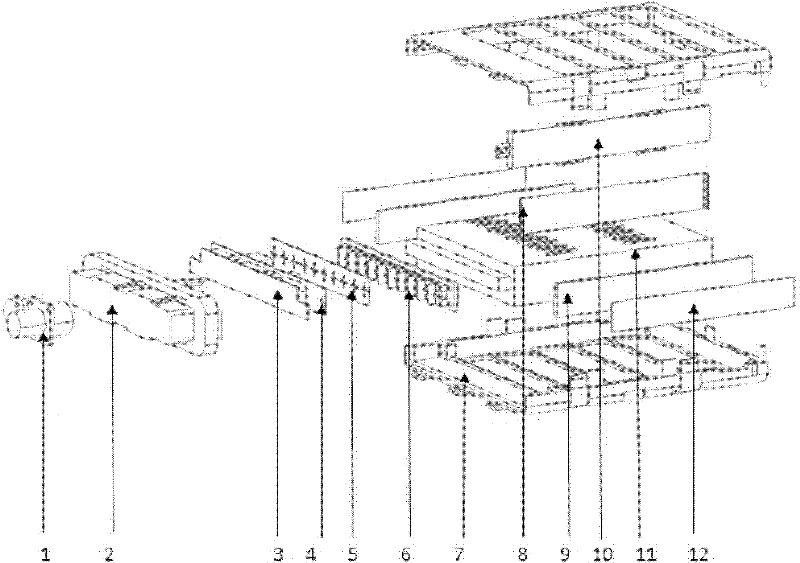
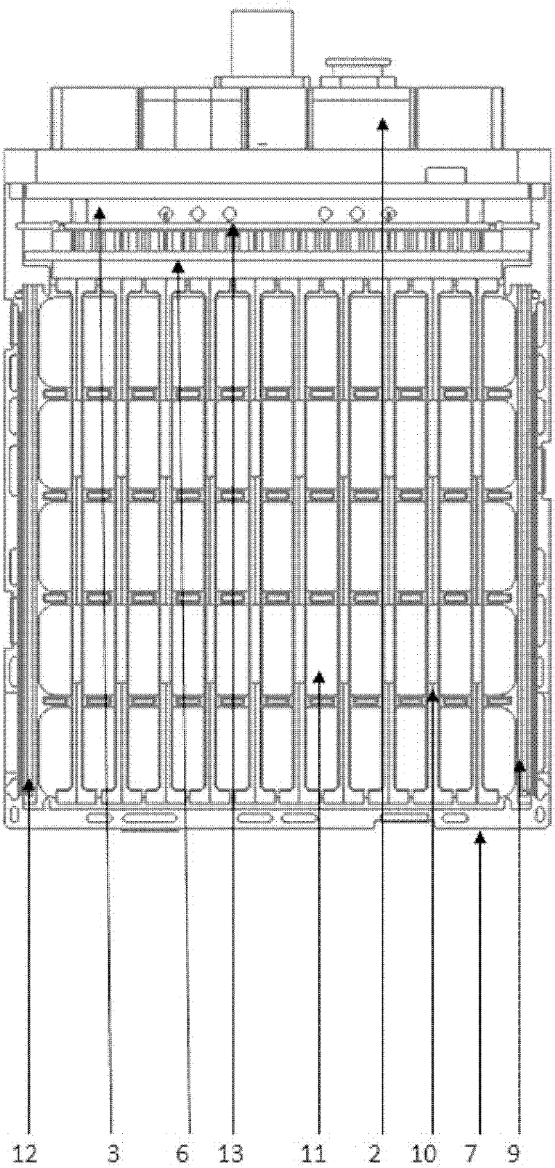
[0016] like figure 1 As shown, the PTC electric heater of the present invention includes a heater frame 7, a PTC heating plate 10, a cooling fin 11, a connector 1 and a controller;
[0017] The frame 7 is made of heat-resistant engineering plastics, and its shape is a square frame structure suitable for the size of an electric vehicle. The spokes provide tension and improve the mechanical strength of the frame.
[0018] The PTC heating plate 10 is composed of two aluminum or stainless steel electrode sheets and a PTC heating chip. The periphery of the two electrode sheets is made of a snap-fit ...
PUM
 Abstract
Description
Claims
Application Information
PatSnap Eureka turns technology decisions into work you can execute. Powered by our Innovation Knowledge Graph, it runs expert workflows across engineering, life sciences, materials and intellectual property. Get your review-ready output in minutes.


