Water-cooled grate combustor

A water-cooled grate and burner technology, applied in the direction of combustion method, combustion equipment, solid fuel combustion, etc., can solve the problems of poor adaptability of coal types, high fuel cost, easy damage to the grate temperature, etc., and achieve the improvement of secondary sufficient Combustion, high fuel utilization rate, and the effect of preventing fuel leakage

Inactive Publication Date: 2012-08-29
冯之军
View PDF5 Cites 4 Cited by
  • Summary
  • Abstract
  • Description
  • Claims
  • Application Information

AI Technical Summary

Problems solved by technology

The main problems are high maintenance rate, poor adaptability of coal types and inability to burn biomass, etc.
When this kind of boiler is shut down, a layer of coal is usually added to the furnace for suffocation, and then the air is supplied when the furnace is started, so this kind of boiler still consumes a large amount of coal when it is shut down.
Moreover, this kind of boiler adds coal to the top of the furnace charcoal fire layer, so that the coal starts to burn from the bottom. Therefore, it is easy to generate black smoke, incomplete combustion, and low thermal efficiency during combustion. The cost of fuel is high, the burden on the user is heavy, and the boiler grate cannot be water-cooled, the grate temperature is too high and easy to damage, the operation reliability is poor, and the furnace needs to be shut down frequently for maintenance, which brings inconvenience to the energy saving, environmental protection and normal use of the coal-fired boiler

Method used


Image

  • Water-cooled grate combustor
  • Water-cooled grate combustor
  • Water-cooled grate combustor

Examples


example 1

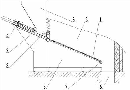
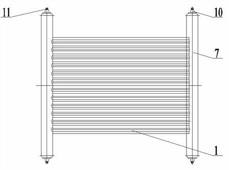
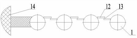
[0019] Such as Figure 1~3 As shown, 1 in the figure is the fixed water-cooled grate, 3 is the hopper at the front of the combustion chamber, 4 is the feeding mechanism in front of the hopper, 5 is the fixed air chamber under the fixed water-cooled grate, and 2 is the upper part of the grate. Combustion chamber, 6 is the ash pit at the front and lower end of the grate; the fixed water-cooled grate 1 is inclined downward by 1 to 30 degrees along the moving direction of the fuel, and the arrangement direction of the fixed water-cooled grate tubes is consistent with the moving direction of the fuel. The upper and lower ends of the water-cooled grate pipe are provided with a water collection box 7 which is vertically connected to it and has a water inlet 10 and a water outlet 11. Between two adjacent fixed water-cooled grate pipes, left and right lap joints, The anti-leakage limiting flaps 12 of planar structure leave air inlet passages 13 on two adjacent limiting flaps. The bott...

example 2

[0024] Depend on Figure 4~5 As shown, it is only a partial structural improvement on the fixed water-cooled grate, and its specific content is: between two adjacent fixed water-cooled grate tubes, an arc-shaped leak-proof limit block 15 overlapping the front and rear is evenly fixed, Leave the air inlet channel 17 (such as Figure 5 Shown), the limit block is an arc structure. Other structures and working process are identical with example 1, so outline it.

[0025] in addition, Figure 4 16 in the hearth is the inner wall.


PUM


Abstract

A water-cooled grate combustor comprises a fixed water-cooled grate, a feed hopper, a feed mechanism, a fixed wind chamber, a combustion chamber and an ash pit, the feed hopper is arranged on the front upper part of the combustion chamber, the feed mechanism is arranged in front of the hopper, the fixed wind chamber is arranged under the grate, the combustion chamber is arranged upon the grate, and the ash pit is arranged at the front lower end of the grate. The technical points are as follows: the fixed water-cooled grate is downwardly inclined by 1 to 30 degrees along the moving direction of fuel, the arrangement direction of the tubes of the fixed water-cooled grate accords with the moving direction of the fuel, headers with water inlets and water outlets are perpendicularly connected with the upper and the lower ends of the tubes of the fixed water-cooled grate, leakage-proof spacing baffles which are lapped at the front and the rear or the left and the right are evenly fixed between each two neighboring tubes of the fixed water-cooled grate, and an intake passage is reserved between each two neighboring spacing baffles. Because the grate of the fixed and inclined water-cooled grate combustor provided by the invention is cooled by water, the grate cannot be burnt out by high temperature, the maintenance rate is low, and coal and biomass can be burnt.

Description

technical field [0001] The invention belongs to the technical field of combustion devices for fuel boilers, in particular to a water-cooled grate burner for a continuous clean combustion device for fuel. Background technique [0002] Existing coal burners mainly include powder injection burners, chain grate burners, reciprocating grate burners, etc. The main problems are high maintenance rate, poor adaptability of coal types and inability to burn biomass. Existing coal-fired boilers usually consist of a furnace, a fire grate, and an air chamber. When this kind of boiler is shut down, a layer of coal is usually added to the furnace for suffocation, and then the air is supplied when the furnace is started. Therefore, when this kind of boiler is shut down, a large amount of coal will still be consumed. Moreover, this kind of boiler is to add coal to the top of the furnace charcoal fire layer, so that the coal starts to burn from the bottom. Therefore, black smoke is easy to b...

Claims


Application Information

Patent Timeline
Patent Type & Authority Applications(China)
IPC IPC(8): F23B50/12F23H3/02
Inventor 冯之军
Owner 冯之军
Why Eureka
Try Eureka