High-temperature high-pressure multiphase flow corrosion testing method and device

A technology of high temperature and high pressure, corrosion experiment, applied in measuring devices, weather resistance/light resistance/corrosion resistance, instruments, etc., it can solve the problems of increasing speed error, inability to simulate field conditions, and inability of corrosive medium to realize pipeline flow, etc. The effect of reliable and stable experimental method on corrosion performance

Inactive Publication Date: 2012-09-05
SOUTHWEST PETROLEUM UNIV
View PDF6 Cites 57 Cited by
  • Summary
  • Abstract
  • Description
  • Claims
  • Application Information

AI Technical Summary

Problems solved by technology

[0005](1) Due to the structural limitations of the high temperature and autoclave body, the corrosive medium cannot realize the pipeline flow and cannot simulate the site conditions;
[0006] (2) The solid phase particles in the corrosive medium will sink to the bottom of the kettle due to gravity, and the samples placed in the gas phase and liquid phase will not be affected by the solid particles. Scouring effect, so it is not possible to simulate on-site erosion and corrosion;
[0007] (3) Although the rotation speed of the agitator and the linear velocity of the sample surface can be accurately calculated, due to the certain viscosity of the corrosive medium, the relative Movement, which makes it difficu

Method used


Image

  • High-temperature high-pressure multiphase flow corrosion testing method and device
  • High-temperature high-pressure multiphase flow corrosion testing method and device
  • High-temperature high-pressure multiphase flow corrosion testing method and device

Examples


Embodiment Construction

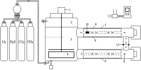
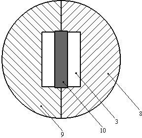
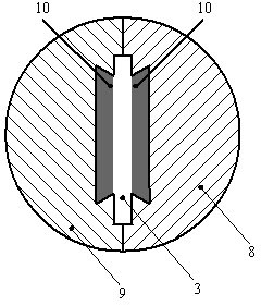
[0024] refer to figure 1 As shown, a high temperature and high pressure multiphase flow corrosion experiment device in the present invention, the main shaft motor 1, the kettle cover 2, the corrosive medium 3, the stirring blade paddle 4, the upper branch pipe 5 of the kettle body, the lower branch pipe 6 of the kettle body, the flow direction of the corrosive medium 7. Upper insulating fixture 8, lower insulating fixture 9, sample 10, ultrasonic flowmeter 11, insulating spacer 12, clamping groove 13; the spindle motor 1 drives the stirring blade 4 to rotate to realize the corrosive medium according to the corrosive medium Flow in the direction shown in the flow direction 7, and simulate the experimental flow rate through the size of the rotating speed; after the upper insulating fixture 8 and the lower insulating fixture 9 are combined, they can be smoothly loaded into the upper branch pipe 5 of the kettle body and the lower branch pipe 6 of the kettle body; The sample 10 is ...


PUM


Abstract

The invention discloses a high-temperature high-pressure multiphase flow corrosion testing method and a high-temperature high-pressure multiphase flow corrosion testing device. The key points are as follows: under high temperature and high pressure conditions, circular flow of a gaseous-phase corrosive medium and a liquid-phase corrosive medium and thorough contact of the two mediums with the surface of a test sample are kept so that the mechanisms of corrosive actions of factors such as flow velocity, tube ponding, and deposited elemental sulphur can be simulated and researched; and the study on the influencing rules of gaseous-phase, liquid-phase, solid-phase and multiphase flows, suspension and suspended particles on the corrosion actions is also included. The testing method and the device are capable of realizing simulation of various corrosive working conditions: measuring the corrosion resistance of a metal material under various corrosive working conditions and in corrosive environments in high-temperature high pressure gaseous-phase, liquid-phase and multiphase flow states, and measuring the corrosion resistance and the corrosion rate of an oil sleeve in exploitation states such as water-carrying exploitation and water-gathered exploitation. Besides, the corrosion resistance of the metal material is comprehensively evaluated under the multiphase flow high-temperature high-pressure corrosion condition; and the preference of the metal material in a specific corrosive environment is realized according to testing results.

Description

technical field [0001] The present invention relates to a high temperature and high pressure multiphase flow corrosion test method and device, more specifically, it relates to a high temperature and high pressure multiphase flow corrosion test method for oil and gas field material corrosion, and the present invention also relates to using the method for high temperature and high pressure corrosion test method Specimen and specimen holder for multiphase flow corrosion experiments and evaluations. Background technique [0002] In the chemical experiment of metal materials, it is necessary to evaluate the corrosion performance of metal materials used in anti-corrosion equipment, pipelines and devices in the petroleum industry and chemical industry in the gas phase, liquid phase or multiphase flow state of high temperature, high pressure and high content of corrosive media. At present, the existing high-temperature and high-pressure corrosion test methods at home and abroad gene...

Claims


Application Information

Patent Timeline
IPC IPC(8): G01N17/00
Inventor 曾德智侯铎张智施太和任建刘飞朱红钧田刚
Owner SOUTHWEST PETROLEUM UNIV
Why Eureka
Try Eureka