
Reference current source capable of providing wide-range operating voltage

A reference current source and working voltage technology, applied in the field of microelectronics, can solve the problems of increased chip cost, large current fluctuation, poor scalability and adaptability, etc., and achieve the effect of easy implementation, simple circuit and wide working voltage range

Inactive Publication Date: 2012-09-05
CHINA KEY SYST & INTEGRATED CIRCUIT
View PDF5 Cites 1 Cited by
  • Summary
  • Abstract
  • Description
  • Claims
  • Application Information

AI Technical Summary

Problems solved by technology

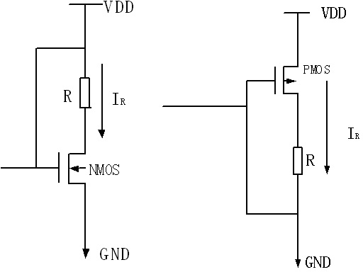
But the disadvantages are: the accuracy is poor, the reference current changes with the power supply, and if the required resistance is large, it will take up more layout area and increase the cost of the chip.
But the disadvantage is: the accuracy of the current reference is very poor, and the current fluctuates greatly with the power supply
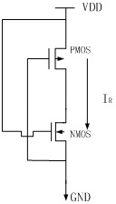
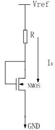
But the disadvantages are: first, a high-precision reference voltage is required, which increases the complexity of circuit implementation, and will bring additional power consumption; second, it cannot work normally under a wide range of operating voltages
But the disadvantages are: first, it cannot work under a wide range of power supply voltage, and second, the circuit structure is relatively complicated
[0015] First, the structure is relatively complex, and a power management module needs to be added, which greatly increases the complexity of the circuit and also increases the implementation cost of the circuit;
[0016] Second, the added power management module will consume power consumption and increase the current of the entire circuit;
[0017] Third, when the working voltage range changes, the power management module needs to be redesigned, and the scalability and adaptability are poor

Method used


Image

  • Reference current source capable of providing wide-range operating voltage
  • Reference current source capable of providing wide-range operating voltage
  • Reference current source capable of providing wide-range operating voltage

Examples


Embodiment Construction

[0037] Such as Figure 6 , Figure 7 Shown are the schematic diagrams of the planar structure and cross-sectional structure of the JFET tube of the reference current source of the present invention, respectively.

[0038] The channel of the JFET tube is low-concentration P-type implantation, which can use the existing layers in the process, such as the Pbase layer or Pbody layer. The P-type channel is completely surrounded by N+ and NWELL, so N+ and NWELL can be regarded as the gate gate of the JFET tube, and one of the two SP injection regions can be regarded as the source end of the JFET tube, and the other can be regarded as the drain of the JFET tube Terminal Drain, the periphery of the SP injection region is the active region TO.

[0039] A special implementation structure of junction field effect transistor (JFET) is proposed, which is a P-channel JFET. In order to realize the reference current, the gate terminal Gate and the source terminal Source of the JFET tube ar...


PUM


Abstract

The invention discloses a reference current source capable of providing wide-range operating voltage, comprising a JFET (junction field effect tube), wherein the structure of the junction field effect tube is a P-channel JFET, a channel is of low-concentration P-type injection, a P-channel is totally surrounded by N+ and NWELL, the N+ and NWELL are taken as a grid end of the JFET, one of two SP injection regions is taken as a source end of the JFET, and the other of the two SP injection regions is taken as a drain end of the JFET; and the grid end and the source end are of short circuit and then are connected to input operating voltage, the source end outputs current and can utilize single or N JEFTs in series connection to be as the reference current source, and an operating voltage range of the reference current source is N*Vp-N*Vb, namely the output is constant current when the input operating voltage is larger than the N*Vp and is smaller than the N*Vb. The reference current source disclosed by the invention has the advantages of capability of realizing a wide operating voltage range, simple circuit, easiness for realizing, no additional power consumption, simple layout realization, expansibility, and capability of meeting the wider operating voltage range.

Description

technical field [0001] The invention relates to the field of microelectronics using a junction field effect transistor as a reference current source, in particular to a reference current source that can provide a wide range of operating voltages. Background technique [0002] In the design of integrated circuits, especially in the design of analog circuits, it is often necessary to use some reference current sources (also called constant current sources), which are mainly used to provide reference currents for various amplifiers inside the circuit, and of course sometimes used for Charge and discharge current for some oscillators or other applications. There are several indicators to measure the performance of the reference current source: the accuracy of constant current (also called constant current characteristics), operating voltage range, temperature characteristics, etc. [0003] The more commonly used implementation methods of the existing reference current sources m...

Claims


Application Information

Patent Timeline
Patent Type & Authority Applications(China)
IPC IPC(8): G05F1/565
Inventor 吴海宏张勇王勇孙锋陈钟鹏曹发兵朱琪韩磊朱奎沈小波从红艳
Owner CHINA KEY SYST & INTEGRATED CIRCUIT
Learn More