
Magnetic suspension damping device

A shock absorbing device and magnetic levitation technology, applied in the direction of spring/shock absorber, magnetic spring, spring, etc., can solve the problems of poor high-frequency vibration isolation effect, inability to adapt to low temperature, complicated inflatable process, etc., and achieve low sealing requirements, Long service life and small size effect

Inactive Publication Date: 2012-09-12
SHENZHEN TYPMAR WIND ENERGY TECH CO LTD
View PDF4 Cites 3 Cited by
  • Summary
  • Abstract
  • Description
  • Claims
  • Application Information

AI Technical Summary

Problems solved by technology

The hydraulic shock absorber moves back and forth in the cylinder through the working piston, so that the friction between the oil in the housing and the inner wall and the internal friction of the oil molecules form a damping force on the vibration. It has better controllability and lower cost. However, The oil will fail due to heat and pollution, and needs to be replaced frequently, and it cannot adapt to low temperature and high temperature environments; the air-filled shock absorber is equipped with a floating piston at the bottom of the cylinder, and is filled in the airtight chamber formed by the floating piston and the end of the cylinder. For high-pressure nitrogen, the oil and gas are completely separated by the large-section O-shaped sealing ring installed on the floating piston, and the compression valve and expansion valve are pushed open by the oil pressure difference between the upper and lower chambers generated by the reciprocating movement of the working piston in the oil. It forms a damping force for vibration, and its comfort is good, but the oil seal requires high requirements, the inflation process is complicated, and it is not easy to maintain
The above two shock absorbers also have the common defects of slow response speed and poor high-frequency vibration isolation effect

Method used


Image

  • Magnetic suspension damping device
  • Magnetic suspension damping device

Examples


Embodiment Construction

[0021] The present invention will be described below in combination with specific embodiments and with reference to the accompanying drawings.

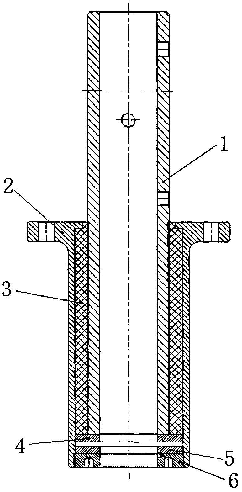
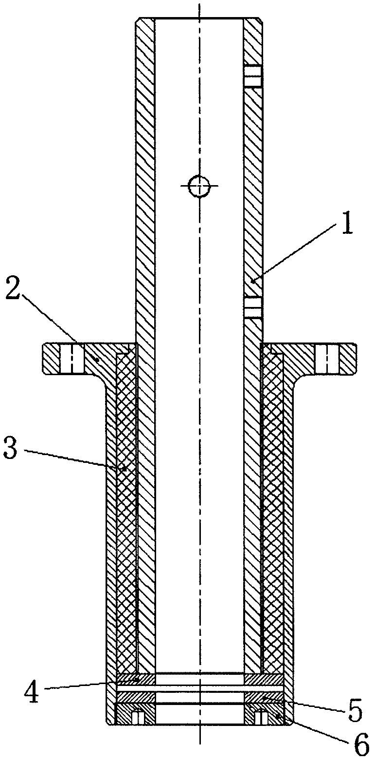
[0022] A magnetic levitation shock absorber used in a high-speed rotating vertical axis maglev wind power generator as shown in the accompanying drawing, including a hollow piston rod 1 made of aluminum alloy, a guide sleeve 3 made of rubber, and a cylinder barrel 2 , the guide sleeve 3 and the hollow piston rod 1 cooperate with each other through threads, the bottom end face of the guide sleeve 3 is aligned with the bottom end face of the hollow piston rod 1, the guide sleeve 3 is used for guiding the hollow piston rod 1, and the radial direction of the hollow piston rod 1 is relieved. Due to the vibration generated by the swing, the outer surface of the guide sleeve 3 and the inner surface of the cylinder 2 are in clearance fit, and the hollow piston rod 1 drives the guide sleeve 3 to move back and forth in the cylinder 2 stably.

...


PUM


Abstract

The invention discloses a magnetic suspension damping device, which comprises a hollow piston rod, a guide sleeve of the hollow piston rod, and a cylinder barrel, wherein the guide sleeve is matched with the hollow piston rod through a thread, the bottom end face of the guide sleeve is flush with the bottom end face of the hollow piston rod, the guide sleeve is used for guiding the hollow piston rod and reducing vibration generated by radial swing of the hollow piston rod, an outer surface of the guide sleeve is in clearance fit with an inner surface of the cylinder barrel, and the guide sleeve is driven by the hollow piston rod to stably reciprocate in the cylinder barrel; and the magnetic suspension damping device is characterized in that two permanent magnet damping pads of which the like magnetic poles are aligned to each other are arranged at the bottom of the interior of the cylinder barrel; and a set separation distance is kept between the two permanent magnet damping pads under the action of repulsion of a magnetic field. The magnetic suspension damping device is simple in structure, small in size, low in cost, high in temperature difference adaptability, low in sealing property requirement, high in response speed and long in service life, applicable to high temperature difference, strong wind, high altitude and other extreme environments, and particularly suitable for damping and buffering a vertical shaft magnetic suspension wind driven generator which is rotated at high speed, and can effectively isolate high-frequency vibration.

Description

technical field [0001] The invention relates to shock absorption, in particular to a magnetic suspension shock absorption device. Background technique [0002] From the perspective of producing damping materials, existing shock absorbers mainly include hydraulic shock absorbers and pneumatic shock absorbers. The hydraulic shock absorber moves back and forth in the cylinder through the working piston, so that the friction between the oil in the housing and the inner wall and the internal friction of the oil molecules form a damping force on the vibration. It has better controllability and lower cost. However, The oil will fail due to heat and pollution, and needs to be replaced frequently, and it cannot adapt to low temperature and high temperature environments; the air-filled shock absorber is equipped with a floating piston at the bottom of the cylinder, and is filled in the airtight chamber formed by the floating piston and the end of the cylinder. For high-pressure nitro...

Claims


Application Information

Patent Timeline
Patent Type & Authority Applications(China)
IPC IPC(8): F16F6/00
Inventor 林文奇陈仕杰彭利文
Owner SHENZHEN TYPMAR WIND ENERGY TECH CO LTD
Learn More