Refrigerant distributor of falling film evaporator for water chilling unit

A technology for falling film evaporators and refrigerant distributors, which is applied to evaporators/condensers, refrigerators, refrigeration components, etc., and can solve complex structures, high processing precision requirements for distributors, and increased manufacturing and processing difficulty and cost. and other issues to achieve high-purity results

Active Publication Date: 2012-09-12
谛卓(北京)咨询顾问有限公司
View PDF6 Cites 7 Cited by
  • Summary
  • Abstract
  • Description
  • Claims
  • Application Information

AI Technical Summary

Problems solved by technology

However, this form of dispenser requires high machining accuracy and high cost
[0008] Chinese Patent Document No. CN 101052854A disclosed a "spray-shaped" refrigerant distributor on October 10, 2007. In this distributor, the refrigerant is sprayed on the evaporation tube with a certain pressure. Although the distributor The structure is simple and the processing technology is not high. However, the design of the distributor is relatively complicated. It is necessary to ensure that each heat exchange tube is sprayed with refrigerant, and at the same time, it is necessary to ensure that the flow field of the entire evaporator will not be affected by the high-speed injection. lead to crossover
However, the structure of some components in the distributor (such as the longitudinally stretched distribution tube and the transversely stretched capillary) is relatively complicated, which increases the difficulty and cost of manufacturing and processing.
In addition, since the components of the distribution parts at all levels are closely connected together, the refrigerant passing through the distributor may still have a large kinetic energy and splash onto the evaporator tube, resulting in uneven distribution.

Method used


Image

  • Refrigerant distributor of falling film evaporator for water chilling unit
  • Refrigerant distributor of falling film evaporator for water chilling unit
  • Refrigerant distributor of falling film evaporator for water chilling unit

Examples


Embodiment Construction

[0029] The present invention will be further described below in conjunction with the accompanying drawings and embodiments.

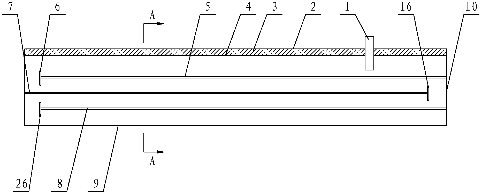
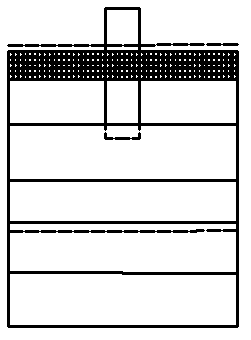
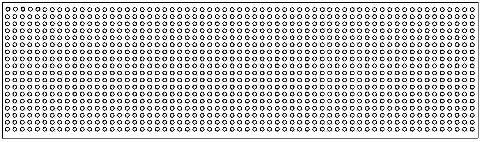
[0030] see Figure 1-Figure 3 , the refrigerant distributor of the falling film evaporator used in this water chiller includes a refrigerant inlet 1, an upper porous top plate 2, a filter screen 3, a lower porous top plate 4, a porous bottom plate 9 and a side plate 10, and the filter screen 3 is sandwiched between Between the upper porous top plate 2 and the lower porous top plate 4, the porous bottom plate 9 is located below the lower porous top plate 4, and the upper porous top plate 2, the filter screen 3, the lower porous top plate 4, the porous bottom plate 9 and the side plates 10 jointly form a chamber. The chamber is provided with more than one distribution orifice plate, and one end of the refrigerant inlet 1 passes through the upper porous top plate 2, the filter screen 3 and the lower porous top plate 4 in sequence, and then opens above the ...


PUM


Abstract

A refrigerant distributor of a falling film evaporator for a water chilling unit comprises a refrigerant inlet, an upper porous top plate, a filter screen, a lower porous top plate, a porous bottom plate and side plates, wherein the filter screen is sandwiched between the upper porous top plate and the lower porous top plate, the upper porous bottom plate is positioned below the lower porous top plate, the upper porous top plate, the filter screen, the lower porous top plate, the porous bottom plate and the side plates jointly encircle to form a cavity, more than one distributing pore plate is arranged in the cavity, one end of the refrigerant inlet is provided with an opening after sequentially penetrating through the upper porous top plate, the filter screen and the lower porous top plate, and the opening is arranged above the distributing pore plates. The distributing pore plates include a primary distributing pore plate, the primary distributing pore plate is connected with the side plates and sequentially divides the cavity into two portions from top to bottom, and a first opening is formed between at least one lateral edge of the primary distributing pore plate and the corresponding side plate. The refrigerant distributor is simple and reasonable in structure, flexible in operation, low in manufacturing cost, fine in refrigerant gas and liquid separation effect and uniform in flow distribution.

Description

technical field [0001] The invention relates to a falling film evaporator, in particular to a refrigerant distributor for a falling film evaporator used in a chiller. Background technique [0002] At present, in large and medium-sized cities, about 30% to 40% of the city's power supply will be consumed during the peak summer electricity consumption of air conditioners, so it is imminent to implement energy conservation for air conditioners. In addition, with the active promotion of national energy conservation and emission reduction policies, as an air-conditioning company, how to reduce refrigerant charge and improve unit energy efficiency has become more and more important. [0003] In recent years, falling film evaporators used in seawater desalination and chemical industries have attracted widespread attention due to their excellent performance, and have begun to emerge in large chillers. Compared with dry evaporators and flooded evaporators , the falling film evaporato...

Claims


Application Information

Patent Timeline
Patent Type & Authority Applications(China)
IPC IPC(8): F25B41/00F25B39/02
Inventor 夏雨亮梁路军王武平张斌
Owner 谛卓(北京)咨询顾问有限公司
Why Eureka
Try Eureka