Discrete transceiver circuit suitable for high-speed 1553 bus

A transceiver circuit and bus technology, applied in the direction of bus network, data exchange through path configuration, etc., can solve the problems of increased system development cost, increased development cycle, poor flexibility, etc., to achieve strong scalability, good versatility, Cost and time savings

Active Publication Date: 2015-01-14
58TH RES INST OF CETC
View PDF2 Cites 1 Cited by
  • Summary
  • Abstract
  • Description
  • Claims
  • Application Information

AI Technical Summary

Problems solved by technology

[0004] The main disadvantages of the 100M 1553 similar to the Extended 1553 and Hyper1553 are: 1. Although there is no need to change the original bus structure, cables, devices, etc., due to the modulation and demodulation carrier transmission mode, the transceiver circuit part needs For relatively large changes, the development cycle will also be greatly increased
[0005] As for SAE's 10M1553, according to the article, its transceiver circuit uses the RS485 bus transceiver, which also has some shortcomings: 1. RS485 is an established protocol standard, and there is no room for change in the protocol, and the terminal resistance, wire There are also clear regulations on length and so on, and the flexibility is poor; 2. Although RS485 can reach a transmission speed of 10Mbps and can also transmit a long distance, it is difficult to ensure that the voltage on the bus reaches the 28Vpp required by the 1553 bus specification during high-speed transmission; 3 1. The transceiver circuit using RS485, its transmission medium is no longer the original 1553 cable, it must be replaced with a dedicated RS485 cable, and the bus interface must also be replaced, which will undoubtedly increase the cost of system development, and will take a long time Time to redeploy the existing 1553 system

Method used


Image

  • Discrete transceiver circuit suitable for high-speed 1553 bus
  • Discrete transceiver circuit suitable for high-speed 1553 bus
  • Discrete transceiver circuit suitable for high-speed 1553 bus

Examples


Embodiment Construction

[0031] The present invention will be further described below in conjunction with drawings and embodiments.

[0032] The present invention adopts the method of building discrete devices, and is divided into two parts: a transmitter and a receiver.

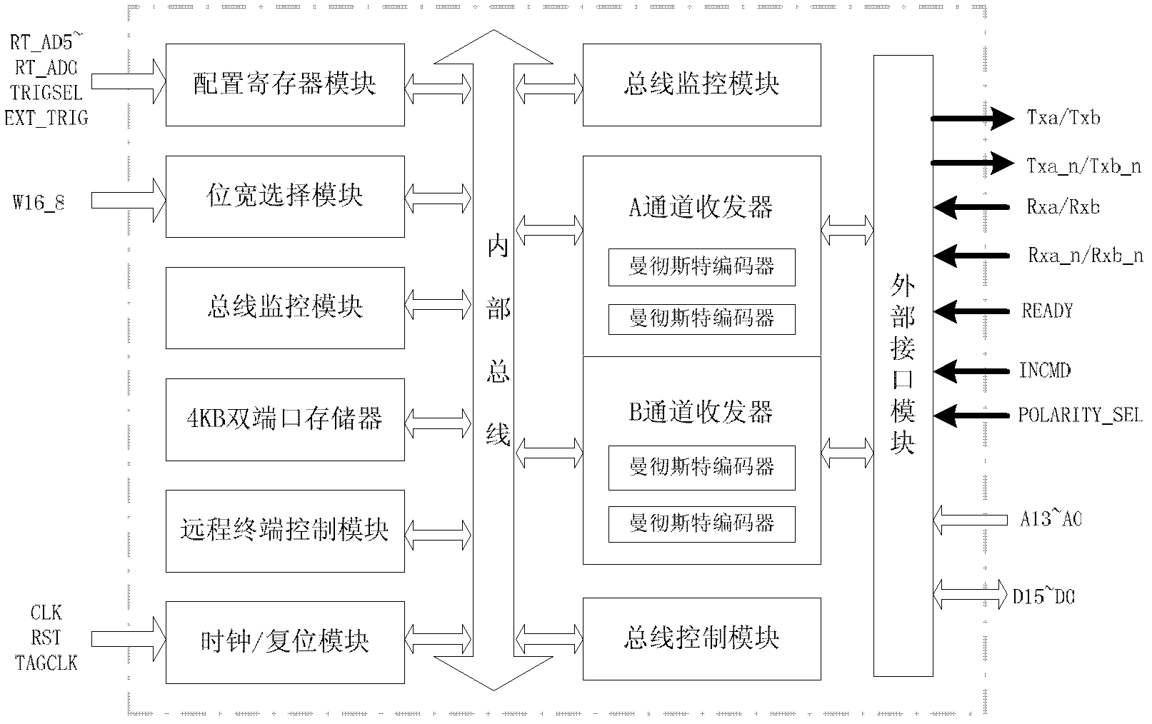
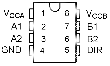
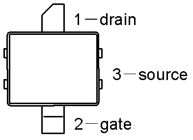
[0033] The transmitter is connected with the protocol processor to complete the transmission of high-speed Manchester code. It consists of a bidirectional voltage conversion driver with three-state output, LDMOS (or NMOS) and resistors / capacitors with certain resistance and capacitance. The structural block diagram of the high-speed protocol processor circuit, and the circuit pin diagram of SN74LVC2T45 and LDMOS-BLF6G21-10G are respectively shown in figure 1 , figure 2 with image 3 .

[0034] Such as figure 1 As shown, the high-speed protocol processor circuit includes: a dual-channel communication protocol processing module, an external interface logic module, a configuration register module, a storage management module, a bi...


PUM


Abstract

The invention aims at overcoming the defects in the prior art and provide a discrete transceiver circuit suitable for a high-speed 1553 bus. The discrete transceiver circuit suitable for the high-speed 1553 bus comprises a transmitter and a receiver; wherein the transmitter is connected with a protocol processor to finish the transmitting of a high-speed Manchester code, and the discrete transceiver circuit also comprises a voltage conversion driving circuit, a lateral double-diffused metal-oxide semiconductor (LDMOS) (or N-metal-oxide-semiconductor (NMOS)) and a resistor / capacitor with certain resistance and capacitance. The receiver comprises a first-order active filter, a comparator, a voltage reference and a voltage conversion driving circuit and is connected with the protocol processor through the voltage conversion driving circuit. The discrete transceiver circuit suitable for the high-speed 1553 bus has the advantages that the discrete transceiver circuit achieves the transmission of 1553 bus data at 10Mbps rate by cooperating with the external protocol processor to work, is built by adopting a discrete device without changing the original bus structure and is flexible and convenient in realization.

Description

technical field [0001] The invention relates to a transceiver circuit, in particular to a discrete transceiver circuit suitable for high-speed 1553 bus. Background technique [0002] MIL-STD-1553 data bus is widely used in aircraft, aviation, aerospace and other fields because of its high reliability and many advantages. In the past half a century, MIL-STD-1553 has been considered as the origin of what we commonly call cyber warfare today. It has realized the information sharing and transmission of various electronic equipment such as sensors, and has fundamentally changed the The way its allies fight. However, with the birth of faster processors, the miniaturization of packaging and the innovation of software technology, the data transmission speed of 1553B, which is only 1Mbps, has undoubtedly become the bottleneck of information and data transmission, and it is imminent to launch a faster transmission method. [0003] The research on the high-speed 1553 bus abroad is re...

Claims


Application Information

Patent Timeline
Patent Type & Authority Patents(China)
IPC IPC(8): H04L12/40
Inventor 魏敬和蔡洁明
Owner 58TH RES INST OF CETC
Why Eureka
Try Eureka