Joint structure for steel pipe pile, steel pipe pile foundation, and method of building steel pipe pile foundation

A steel pipe and sheet pile technology is applied in the field of steel pipe sheet pile joint construction, which can solve the problems of decreased shear yield strength of joints, decreased adhesion of joint steel pipes and T-shaped steels to mortar, etc., so as to improve the shear yield strength and realize construction Cost, effect of high shear yield strength

Inactive Publication Date: 2012-09-12
NIPPON STEEL CORP
View PDF5 Cites 2 Cited by
  • Summary
  • Abstract
  • Description
  • Claims
  • Application Information

AI Technical Summary

Problems solved by technology

In this case, the adhesive force between the joint steel pipe and the T-section steel at the joint and the mortar decreases, and the shear yield strength of the joint further decreases.

Method used


Image

  • Joint structure for steel pipe pile, steel pipe pile foundation, and method of building steel pipe pile foundation
  • Joint structure for steel pipe pile, steel pipe pile foundation, and method of building steel pipe pile foundation
  • Joint structure for steel pipe pile, steel pipe pile foundation, and method of building steel pipe pile foundation

Examples


no. 1 Embodiment approach )

[0063] Hereinafter, the steel pipe sheet pile joint structure 1 concerning 1st Embodiment of this invention is demonstrated based on drawing.

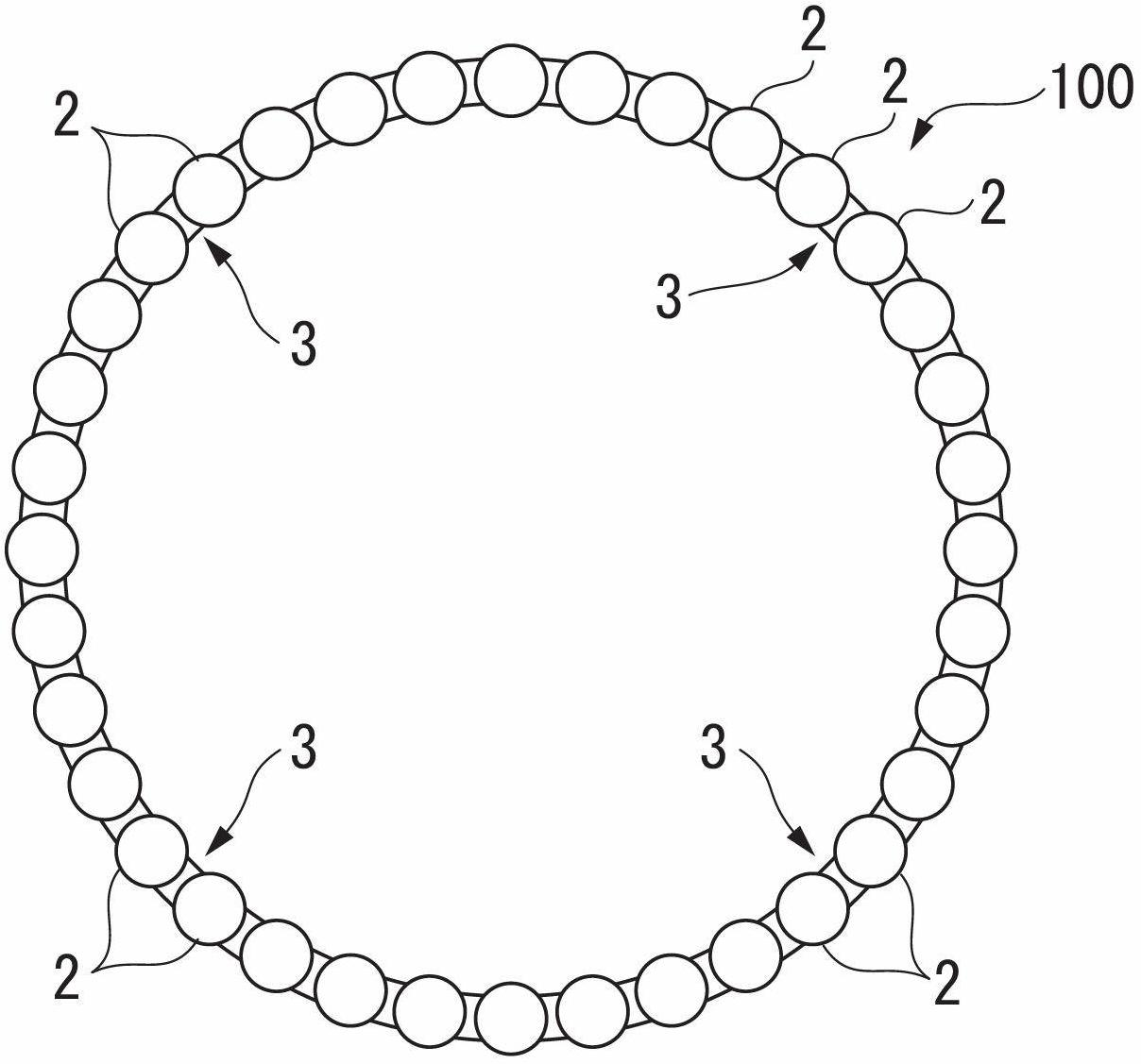
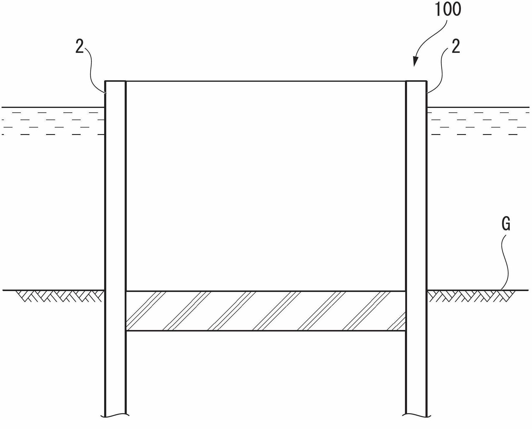
[0064] Figure 1A shows the steel pipe sheet pile foundation 100 constructed using the steel pipe sheet pile joint structure 1 according to this embodiment, Figure 1B is along Figure 1A The cross-sectional view obtained by the D-D line. This steel pipe sheet pile foundation 100 is a caisson foundation supporting a bridge pier installed near a river or near a coast, etc., and a plurality of steel pipe sheet piles 2 penetrating into a foundation G on a river bottom or a seabed are arranged in a circular shape in plan view, And these steel pipe sheet piles 2 are mutually connected via the joint part 3, and are comprised.

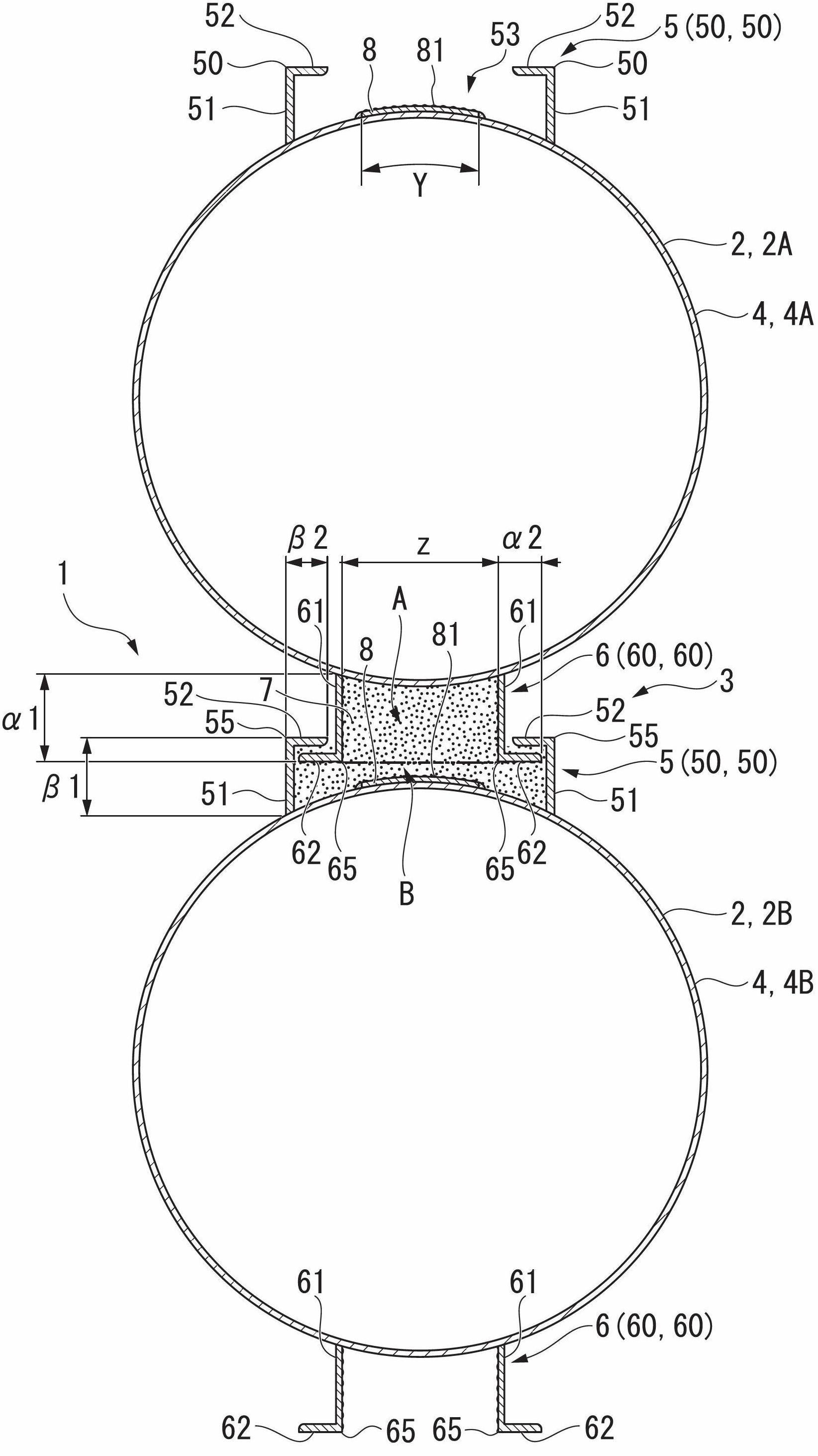
[0065] figure 2 It is a cross-sectional view showing the steel pipe sheet pile joint structure 1 according to this embodiment. The joint part 3 in this steel pipe sheet pile joint structure 1 will have a first ste...

no. 2 Embodiment approach )

[0096] Hereinafter, a second embodiment of the present invention will be described based on the drawings.

[0097] In the steel pipe sheet pile joint structure 1 according to the first embodiment, if figure 2 As shown, the first steel pipe sheet pile 2A and the second steel pipe sheet pile 2B each have a male joint 6 and a female joint 5 . On the other hand, in the steel pipe sheet pile joint structure 1' according to the second embodiment, as Figure 8 As shown, the first steel pipe sheet pile 2A' has a pair of female joints 5,5, and the second steel pipe sheet pile 2B' has a pair of male joints 6,6. About other structures, it is the same as the structure demonstrated in 1st Embodiment.

[0098] When constituting the foundation using the steel pipe sheet pile joint structure 1' according to this embodiment, it is preferable to construct it in the following procedure.

[0099] (1) if Figure 9A As shown, the main pipes 4A', 4A' having a pair of female joints 5, 5 are cont...

Embodiment

[0107] Hereinafter, examples of the present invention will be described.

[0108] In this embodiment, the effect of providing the steel plate 8 having the protrusion 81 between the female side legs 51 and 51 of the female joint 5 and the effect of making the width dimension Y of the plate member 8 smaller than the male side leg 61 were confirmed. The effect is twice the sum of the length dimension α1 and the length dimension α2 of the male side arm portion 62 .

[0109] First, the test body will be described. First, when making the test body of the embodiment, as Figure 10 and Figure 11 As shown, a pair of pillars 91 having an arcuate surface 92 with a radius of about 600 mm on one side and a load column 93 having an arcuate surface 94 having the same curvature as the arcuate surface 92 on opposite sides are prepared. In addition, male joints 6 each composed of a pair of L-shaped steel materials 60 and 60 are respectively fixed to the arcuate surface 92 of one support col...


PUM


Abstract

A joint structure for a steel pipe pile, comprising: a steel pipe pile's first main pipe; a steel pipe pile's second main pipe which is adjacent to the steel pipe pile's first main pipe; a male joint which is provided with a pair of male legs mounted to the steel pipe pile's first main pipe and also with a pair of male arms extending from the male legs so as to separate from each other, and which has protrusions and depressions formed on the surface thereof; a female joint which is provided with a pair of female legs mounted to the steel pipe pile's second main pipe and also with a pair of female arms extending from the female legs so as approach each other, and which is engaged with the male joint; and a plate-like member which is provided to the steel pipe pile's second main pipe at a position between the pair of female legs, and which has protrusions and depressions formed on the surface thereof.

Description

technical field [0001] The invention relates to a steel pipe sheet pile joint structure, a steel pipe sheet pile foundation, and a construction method for a steel pipe sheet pile foundation. [0002] This application claims priority based on Japanese Patent Application No. 2009-272215 for which it applied in Japan on November 30, 2009, and uses the content here. Background technique [0003] In general, the steel pipe sheet piles are used by (1) fixing circular joint steel pipes with slits to adjacent steel pipe sheet piles, and (2) continuously embedding steel pipe sheet piles in the joint pipes while fitting these joint steel pipes A steel pipe sheet pile joint structure obtained by excavating the sand and soil in the joint steel pipe, (4) cleaning the joint steel pipe, and (5) filling the joint steel pipe with mortar in the ground. Such a steel pipe sheet pile joint structure is called a P (pipe)-P (pipe) joint (P-P joint) because joint steel pipes (P: pipe) are fitted t...

Claims


Application Information

Patent Timeline
Patent Type & Authority Applications(China)
IPC IPC(8): E02D5/08
CPCE02D5/28E02D5/285
Inventor 石滨吉郎西海健二山下久男寺本泰章岩村荣世村井健二竹内聪永岛聪志
Owner NIPPON STEEL CORP
Why Eureka
Try Eureka