Al technical title is built by PatSnap Al team. It summarizes the technical point description of the patent document.
A monitoring device and acoustic emission technology, which is applied to the parts of grinding machine tools, grinding/polishing equipment, metal processing equipment, etc., can solve the problems of signal coolant flow and pressure interference, poor versatility, and changing the structure of the grinding wheel, etc., to achieve Eliminate contact surface gaps, facilitate installation, and reduce reflection loss
Inactive Publication Date: 2015-03-11
XIAMEN UNIV
View PDF4 Cites 0 Cited by
Summary
Abstract
Description
Claims
Application Information
AI Technical Summary
This helps you quickly interpret patents by identifying the three key elements:
Problems solved by technology
Method used
Benefits of technology
Problems solved by technology
The device is limited by cooling conditions and can only be used for wet grinding, and the collected signals will be interfered by the flow and pressure of coolant
At present, the research work also installs piezoelectric acoustic emission sensors around the grinding wheel for grinding acoustic emission monitoring. This method can collect acoustic emission signals with a high signal-to-noise ratio, but it needs to change the structure of the grinding wheel, which has poor versatility.
Method used
Image
Click on the blue label to locate the original text in one second.
Reading with bidirectional positioning of images and text.
Examples
Embodiment Construction
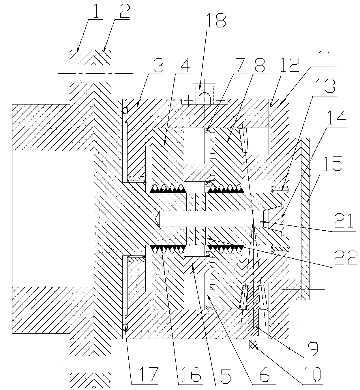
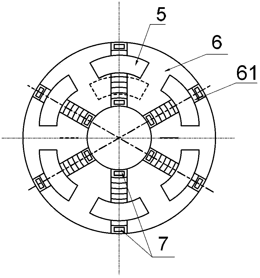
[0022] see figure 1 and 2 , the embodiment of the present invention is provided with a locking flange 1, a magnetic shaft 2, a housing 3, an annular magnetic pole 4, 6 permanent magnet blocks 5, a magnetic slide disc 6, a limit block 7, an annular conical magnetic pole 8, a cone Gear 9, handle 10, retaining ring 11, plug 14, end cap 15, magnetorheological fluid 16, acoustic emission sensor seat 18, acoustic emission sensor (not shown in the figure) and detection circuit (not shown in the figure).
[0023] The locking flange 1 is locked with the external grinding wheel. The left end of the magnetic rotating shaft 2 is connected with the locking flange 1. The magnetic rotating shaft 2 is provided with a hollow hole 21. The opening end of the hollow hole 21 is provided with a plug 14. The hollow hole 21 is filled with magnetorheological fluid. The hollow hole 21 is connected to the outer surface of the magnetic rotating shaft 2. It communicates with four radial holes 22 . The ...
PUM
Abstract
The invention discloses a grinding wheel grinding sound emission monitoring device, and relates to a sound emission monitoring device. The grinding wheel grinding sound emission monitoring device comprises a locking flange, a magnetic rotation shaft, a shell, an annular magnetic pole, a permanent magnet, a magnetic slide plate, a limited block, an annular conical surface magnetic pole, a bevel gear, a handle, a retainer ring, a plug, an end cover, magnetorheological fluids, a sound emission sensor seat, a sound emission sensor and a detection circuit, the locking flange is locked with an external grinder grinding wheel, the left end of the magnetic rotation shaft is connected with the locking flange, the magnetic rotation shaft is provided with a hollow hole, the plug is arranged at an opening end of the hollow hole, the magnetorheological fluids are stored in the hollow hole, the hollow hole is communicated with the outer surface of the magnetic rotation shaft, the shell is sleeved on the magnetic rotation shaft, both the annular magnetic pole and the annular conical surface magnetic pole are positioned in the shell and are sleeved on the magnetic rotation shaft, the left end of the annular conical surface magnetic pole is connected with the magnetic slide plate, the left end of the magnetic slide plate is connected with the permanent magnet in a threaded manner, the right end of the annular conical surface magnetic pole is meshed with the bevel gear, and the detection circuit is arranged outside the shell and is electrically connected with the sound emission sensor.
Description
technical field [0001] The invention relates to an acoustic emission monitoring device, in particular to a grinding wheel grinding acoustic emission monitoring device. Background technique [0002] With the development of modern science and technology, high-performance optical surfaces of various specifications have been widely used in military and civilian fields, and the existing manufacturing level is difficult to meet the increasing demand in quality and quantity. Low-cost mass production of high-quality optical components has become an urgent problem in the optical manufacturing industry. [0003] Diamond grinding wheel grinding is the main processing method of optical components. Based on the dynamic signal feature extraction and recognition technology in the grinding wheel grinding process, online monitoring and control of the grinding state is an effective way to improve the efficiency of optical surface processing. During the grinding process, the damage and wear o...
Claims
Application Information
Patent Timeline
Application Date:The date an application was filed.
Publication Date:The date a patent or application was officially published.
First Publication Date:The earliest publication date of a patent with the same application number.
Issue Date:Publication date of the patent grant document.
PCT Entry Date:The Entry date of PCT National Phase.
Estimated Expiry Date:The statutory expiry date of a patent right according to the Patent Law, and it is the longest term of protection that the patent right can achieve without the termination of the patent right due to other reasons(Term extension factor has been taken into account ).
Invalid Date:Actual expiry date is based on effective date or publication date of legal transaction data of invalid patent.