Converter with power factor correction

一种转换器、变压器的技术,应用在输出功率的转换装置、直流功率输入变换为直流功率输出、高效电力电子转换等方向,能够解决窄输入电压范围等问题,达到降低开销、高效率的效果

Inactive Publication Date: 2012-09-12
SIEMENS AG
View PDF5 Cites 3 Cited by
  • Summary
  • Abstract
  • Description
  • Claims
  • Application Information

AI Technical Summary

Problems solved by technology

In addition to a narrow input voltage range, such converters also have undesired losses due to the reloading process (Umladungsvorgaenge)

Method used


Image

  • Converter with power factor correction
  • Converter with power factor correction
  • Converter with power factor correction

Examples


Embodiment Construction

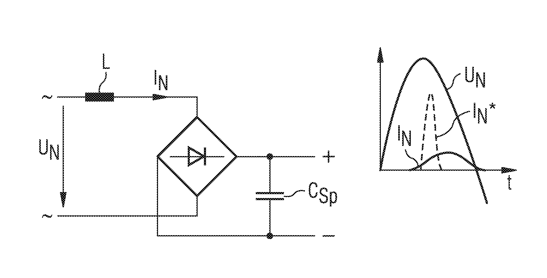
[0038] 1-3 show known PFC circuits which convert an input AC voltage into an intermediate circuit DC voltage. In the case of a passive circuit ( FIG. 1 ), a sufficiently large inductor L is arranged before the rectifier unit. The conduction angle varies in this way with respect to the original current curve I N * is increased, but a phase shift to be considered occurs therein.

[0039] The active circuit (Figures 2a and 2b) includes a clock-controlled switch S, by means of which the current I can be influenced in addition to the conduction angle N phase.

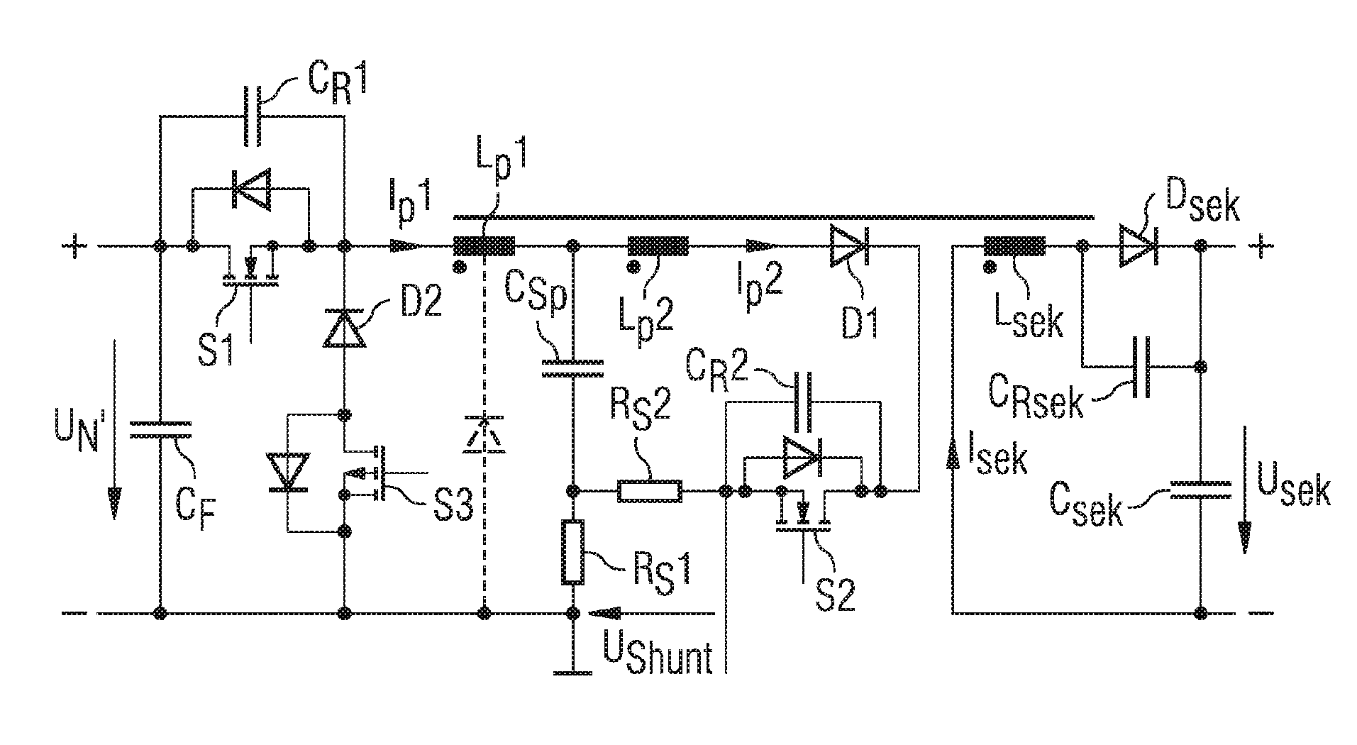
[0040] exist image 3 The converter shown in includes a rectifier bridge on the input side, which is connected to the AC voltage U N on and the AC current I N converted into a rectified current I N '. A filter capacitor C is connected downstream of the rectifier bridge F , the filter capacitor C F are dimensioned with respect to the AC voltage U N The frequency is small. The filter capacitor C F It can also advan...


PUM


Abstract

The invention relates to a converter for converting an input-side alternating current (UN) into an output-side DC current (Usek), a power factor correction being provided and the converter comprises a transformer having at least two serially arranged primary windings (Lp1, Lp2). Also, a first switch (S1) is used to switch a storage capacitor unit (CSp) in series with a first primary winding (Lp1) to the alternating current (UN) in a clocked manner via rectification elements (GD1, GD2, GD3, GD4) and a second primary winding (Lp2) can be switched to the storage capacitor unit (CSp) in a clocked manner by means of a second switch (S2).

Description

technical field [0001] The invention relates to a converter for converting an input-side AC voltage into an output-side DC voltage, wherein power factor correction is provided and the converter comprises a transformer with at least two primary windings arranged in series. Furthermore, the invention relates to a method for operating such a converter. Background technique [0002] Converters used in conventional mains supply systems usually have strongly harmonically charged input currents or a power factor significantly below unity. The reason for this is the need to recharge the DC-side storage capacitor via the AC-side rectifier. Short, needle-shaped current peaks are the result. Without additional measures, the height of the current peaks is only limited by the internal resistance of the input-side grid, grid filter, rectifier and storage capacitor. [0003] In order to reduce the proportion of interfering harmonics in the current consumption of the converter, a so-call...

Claims


Application Information

Patent Timeline
Patent Type & Authority Applications(China)
IPC IPC(8): H02M3/335
CPCH02M3/33569Y02B70/10Y02P80/10H02M3/01H02M3/335
Inventor C.奥格斯基
Owner SIEMENS AG
Why Eureka
Try Eureka