Built-in material liquid conveying pump under negative working condition

A material-liquid delivery pump, built-in technology, applied in the direction of rotary piston pumps, pumps, rotary piston/swing piston pump components, etc., can solve explosion accidents, cannot deliver material and liquid to designated locations, and centrifugal delivery Problems such as poor cavitation compatibility of the material pump, etc., to achieve the effect of meeting the sealing requirements

Active Publication Date: 2012-09-19
吴国存
View PDF4 Cites 2 Cited by
  • Summary
  • Abstract
  • Description
  • Claims
  • Application Information

AI Technical Summary

Problems solved by technology

[0005] Chinese patent (patent number CN 1583207 A) discloses an internal circulation falling film distillation equipment: the axial flow pump belongs to the centrifugal feed pump, which is not suitable for sucking and discharging the feed liquid that is about to evaporate, because local negative pressure will inevitably be generated when the feed is sucked , when the local negative pressure is lower than the vapor pressure of the evaporating feed liquid at this temperature, the feed liquid will undergo a certain gasification phenomenon, thus causing cavitation in the impeller chamber of the feed pump. The compatibility with cavitation is very poor, so when the cavitation phenomenon reaches a certain level, the delivery pump cannot deliver the material liquid to the designated place
[0006] The power input shaft of the axial flow pump communicates with the outside world, and the pot cover with sealing measures is a single packing sealing structure according to the structure shown in the attached figure, so it is difficult to ensure the sealing performance of the device under high vacuum. Once the outside air is excessively inhaled under certain working conditions, it is easy to cause an explosion accident.

Method used


Image

  • Built-in material liquid conveying pump under negative working condition
  • Built-in material liquid conveying pump under negative working condition
  • Built-in material liquid conveying pump under negative working condition

Examples


Embodiment 1

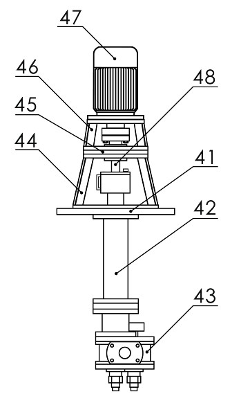
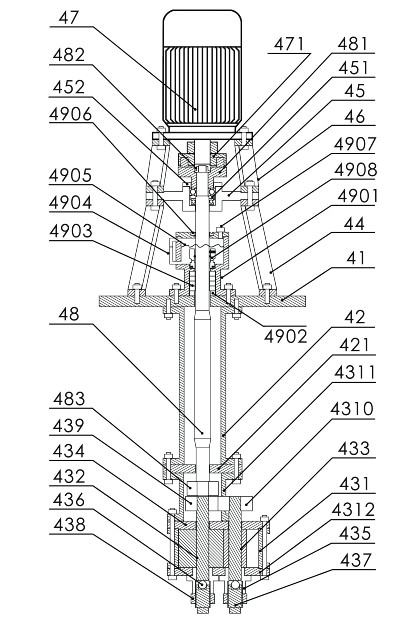
[0023] In this embodiment, a built-in negative pressure working condition feed liquid delivery pump, refer to the attached figure 1 , figure 2 and Figure 4 , in the figure: large cover 41, extension sleeve 42, positioning plate 421, pump head 43, pump cylinder housing 431, active rotor shaft 432, passive rotor shaft 433, pump body front end cover 434, shaft sleeve 435, pressure bearing 436 , Adjusting the top wire 437, adjusting the top wire lock nut 438, the driving gear 439, the driven gear 4310, the dial sleeve 4311, the rear end cover of the pump body 4312, the bearing bracket 44, the bearing housing 45, the bearing assembly 451, the bearing gland 452, power mechanism bracket 46, power mechanism 47, power mechanism dial 471, pump shaft 48, upper dial 481, dial lock nut 482, lower dial 483, sealing shell 4901, packing top ring 4902, sealing packing 4903 , Liquid level gauge 4904, sealing material liquid 4905, oil seal 4906, material liquid adding bolt 4907, mechanical s...

Embodiment 2

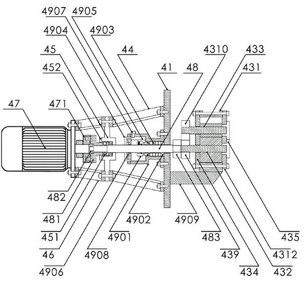
[0071] See attached image 3 , in the figure: large cover 41, pump head 43, pump cylinder housing 431, active rotor shaft 432, passive rotor shaft 433, pump body front cover 434, shaft sleeve 435, driving gear 439, driven gear 4310, pump body rear end Cover 4312, bearing seat bracket 44, bearing seat 45, bearing assembly 451, bearing gland 452, power mechanism bracket 46, power mechanism 47, power mechanism dial 471, pump shaft 48, upper dial 481, dial lock nut 482 , Lower dial 483, sealing shell 4901, packing top ring 4902, sealing packing 4903, liquid level gauge 4904, sealing material liquid 4905, oil seal 4906, feeding liquid adding bolt 4907, mechanical seal 4908, pump head bracket 4909.

[0072] The difference between this embodiment and the built-in negative pressure working condition feed liquid delivery pump structure in Embodiment 1 is that some components have increased or decreased due to changes in the use angle.

[0073] The built-in negative pressure working co...


PUM


Abstract

The invention relates to a material liquid conveying pump, in particular to a built-in material liquid conveying pump under a negative working condition. The built-in material liquid conveying pump under the negative working condition comprises a big cover, an elongated sleeve, a pump head, a bearing base support, a bearing base, a power mechanism support, a power mechanism, a pump shaft and a sealing casing, wherein the sealing casing is connected on one side of the big cover; the pump shaft penetrates through one end of the sealing casing and is connected with the power mechanism; the other end of the pump shaft is connected with the pump head; a sealing component and sealing material liquid are arranged between the sealing casing and the pump shaft; and the pump head has a volumetric structure. Compared with the prior art, the built-in material liquid conveying pump under the negative working condition has the advantages that: by adopting the structure that the big cover is connected with the sealing casing and the pump shaft penetrates through the sealing casing and is connected with the power mechanism, a sealing requirement of a decompressive short-path distilling device at a high temperature and a high vacuum degree can be met, no leakage of outside air into a vacuum heating tank can be absolutely ensured, and when the material liquid to be evaporated is sucked and exhausted, even through a certain degree of cavitation is caused, and the material liquid can be conveyed to an appointed position through the volume change of the pump cylinder.

Description

[0001] Technical field: [0002] The invention relates to a feed liquid delivery pump, in particular to a built-in feed liquid delivery pump under negative pressure working conditions. Background technique: [0003] Distillation is a simple and efficient method of physical purification and separation. The gasification of the material-liquid medium is related to the ambient temperature and ambient air pressure. At the same temperature, the lower the pressure, the more conducive to the gasification of the liquid material medium. Whether the medium can be efficiently collected is related to the process distance and process angle from the liquid level of the feed medium to the distillate collection device. The shorter the process distance and the lower the process angle, the more conducive to the efficient recovery of the gasified medium. The recovery of the gasification medium under the long process distance under the vertical process angle has the lowest recovery efficiency, s...

Claims


Application Information

Patent Timeline
IPC IPC(8): B01D3/00F04C2/14F04C15/00
Inventor 吴国存
Owner 吴国存
Why Eureka
Try Eureka