Coating damping cutter rod and damping testing method thereof

A tool holder and damping technology, which is applied in the field of cutting tools, can solve problems such as unsatisfactory processing conditions, poor vibration damping effect and adaptability, and complex structure, so as to improve machining accuracy and efficiency, suppress vibration, and improve The effect of stability

Inactive Publication Date: 2012-09-19
SHANDONG UNIV
View PDF8 Cites 11 Cited by
  • Summary
  • Abstract
  • Description
  • Claims
  • Application Information

AI Technical Summary

Problems solved by technology

[0008] The object of the present invention is to provide a coated damping and vibration-reducing tool-shank and its vibration-damping test method in order to overcome the shortcomings of the above-mentioned existing vibration-damping tool-shank with complex structure, poor vibration-damping effect and adaptabili

Method used


Image

  • Coating damping cutter rod and damping testing method thereof
  • Coating damping cutter rod and damping testing method thereof
  • Coating damping cutter rod and damping testing method thereof

Examples


Embodiment 1

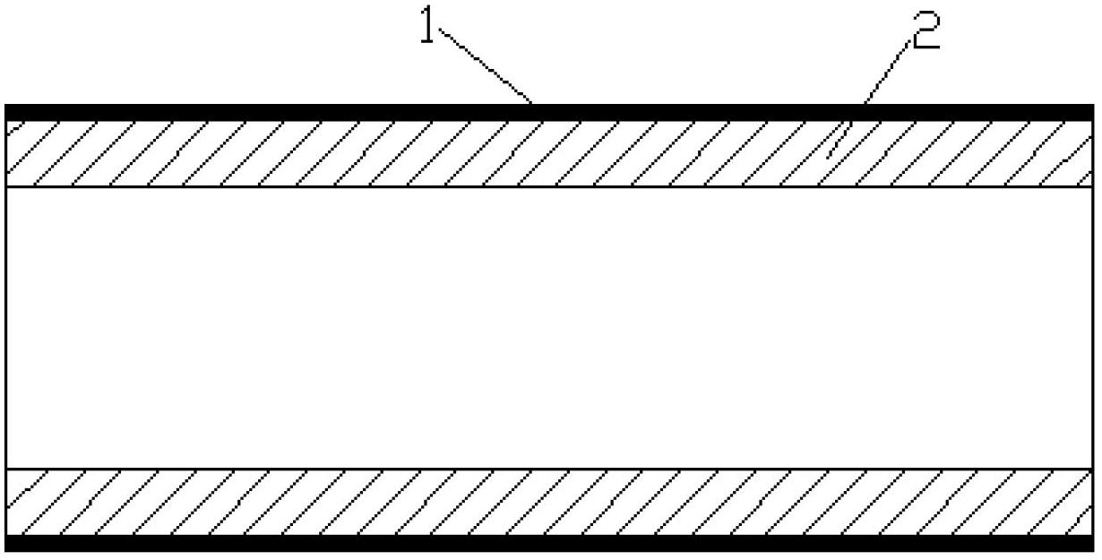
[0041] Embodiment 1: Taking the boring bar with obvious self-excited vibration in the machining process as an example, a coated damping and vibration-absorbing boring bar is designed. The coating method is cylindrical boring bar 3 outer coating 1. The hollow boring bar 3 has an aspect ratio of 6:1, an outer diameter of φ30mm, and an inner diameter of φ20mm. The base material is 40Cr alloy structural steel, and its elastic modulus E s =200GPa, loss factor η s =0.0001, damping ratio ζ s =0.015; the outer coating damping material is M2052 alloy, the modulus of elasticity E c =50GPa, loss factor η c =0.23, coating thickness H c =0.1mm.

[0042] Such as Figure 5 In the cross-sectional structure of the outer coating 1 of the boring bar 3 shown, the overall loss factor η of the coating damping and damping boring bar is calculated according to the following formula:

[0043] η = ( E ...

Embodiment 2

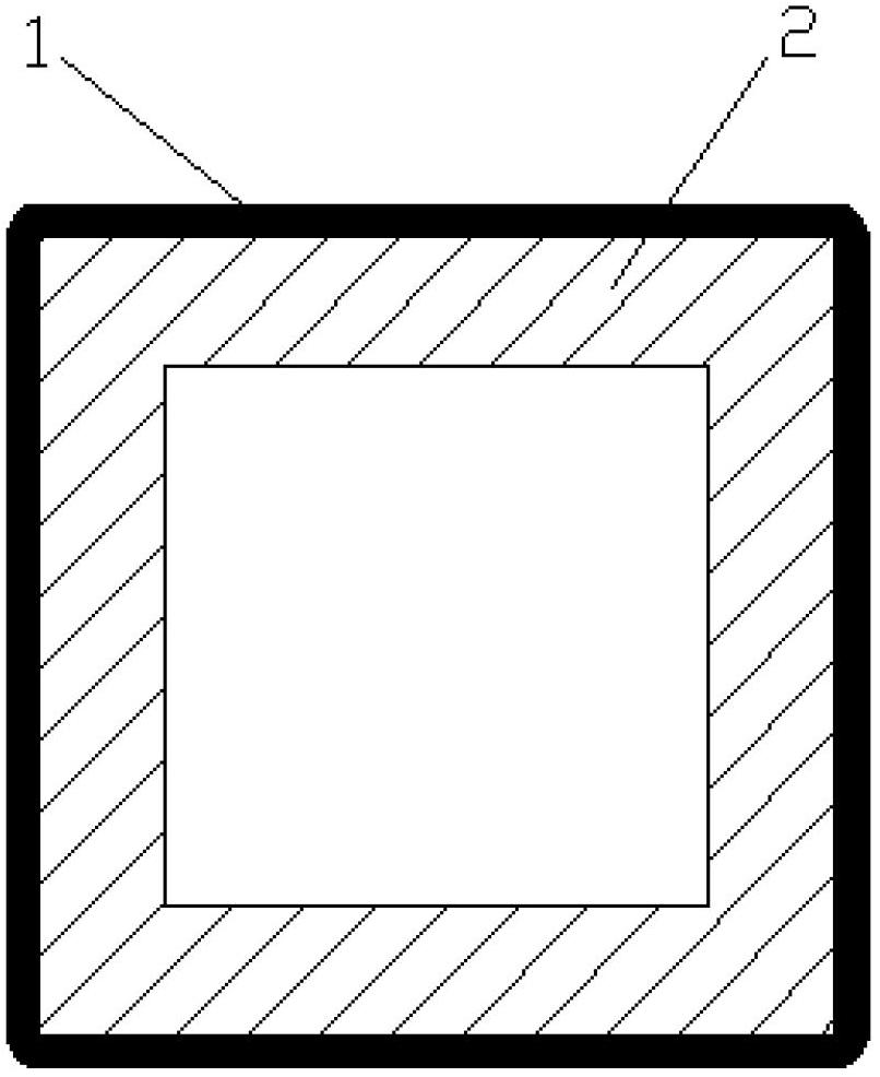
[0048] Embodiment 2: According to image 3 Design a coating damping and vibration reduction turning tool holder. The coating thickness H of the inner wall of the turning tool holder is applied by thermal spraying process c =0.15mm Ni-Ti alloy, improve the damping characteristics of the turning tool holder, so as to achieve the purpose of reducing vibration. The base material of the tool holder is 40Cr alloy structural steel, and the loss factor η s =0.0001; coating damping material is Ni-Ti alloy, loss factor η c =0.18, coating thickness H c =0.15mm. The vibration-damping turning tool holder is mainly used for vibration reduction and noise reduction of the turning tool holder in the machining process.

Embodiment 3

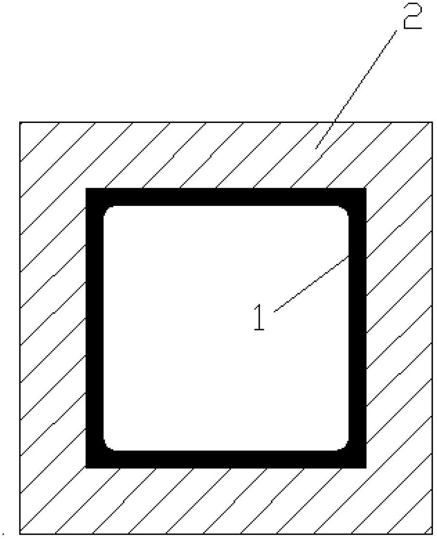
[0049] Embodiment 3: according to Image 6 A coated damping and vibration-absorbing milling cutter bar is designed as shown. Coating thickness H on the periphery of the milling cutter shank c =0.1mm Fe-Cr alloy. Fe-Cr alloy is a high damping alloy material with strong vibration damping ability, which can improve the vibration resistance of the milling cutter shaft. The base material of the tool holder is hard alloy. The vibration-damping tool holder is mainly used for vibration and noise reduction of the milling tool holder.


PUM

PropertyMeasurementUnit
Outer diameter φaaaaaaaaaa
Inner diameter φaaaaaaaaaa
Elastic modulusaaaaaaaaaa

Abstract

The invention discloses a coating damping cutter rod. On the base material of the cutter rod is coated a damping material layer which forms a lamination structure together with the base material of the cutter rod to increase cutter rod damping, and vibration kinetic energy of the cutter rod is converted into heat energy by use of coating damping material internal friction, to achieve the purposes of damping, improving machining efficiency and improving machining quality. The inventive coating damping cutter rod can adapt to complex variable machining conditions, effectively reduce or suppress cutter rod vibration during the cutting process, improve stability of the cutting process, and improve machining precision and machining efficiency. The invention also discloses a damping testing method of the damping cutter rod.

Description

technical field [0001] The invention relates to a cutting tool, in particular to a coated damping and vibration-reduction cutter rod and a vibration-reduction testing method thereof. Background technique [0002] At present, inner hole machining or inner cavity machining is a common and widely used processing method in mechanical processing, and deep hole or deep cavity machining is often the biggest difficulty in inner hole or inner cavity machining. In the process of deep hole or deep cavity machining, slender internal turning tools or milling rods and boring bars with large length-to-diameter ratio are usually used, so the dynamic stiffness of the processing tools is often too low, so cutting chatter is easy to occur And can not meet the processing requirements. Generally speaking, when the length-to-diameter ratio of the cutter bar is less than 4, there will be no vibration during the processing or the vibration will generally not affect the processing quality. However...

Claims


Application Information

Patent Timeline
IPC IPC(8): B23B29/00B23B29/02G01M7/02
Inventor 刘战强夏峰
Owner SHANDONG UNIV
Why Eureka
Try Eureka