Preparation method of artificial microtube and application of artificial microtube as micromotor

A technology of artificial micro and micro motors, which is applied in the direction of mechanical equipment, microstructure technology, microstructure devices, etc., can solve the problems of small synthesis quantity at one time, difficult operation requirements of particle beam spraying method, and high cost, and achieve low cost and small size Controllable, easy-to-operate effects

Inactive Publication Date: 2012-09-19
HARBIN INST OF TECH
View PDF4 Cites 15 Cited by
  • Summary
  • Abstract
  • Description
  • Claims
  • Application Information

AI Technical Summary

Problems solved by technology

[0003] The present invention aims to solve the technical problems of high cost and relatively small number of synthetic micro-nano motors in the existing electrochemical deposition

Method used


Image

  • Preparation method of artificial microtube and application of artificial microtube as micromotor
  • Preparation method of artificial microtube and application of artificial microtube as micromotor
  • Preparation method of artificial microtube and application of artificial microtube as micromotor

Examples


specific Embodiment approach 1

[0014] Specific embodiment one: the preparation method of the artificial microtube of the present embodiment is carried out according to the following steps:

[0015] 1. Preparation of metal catalytic particles;

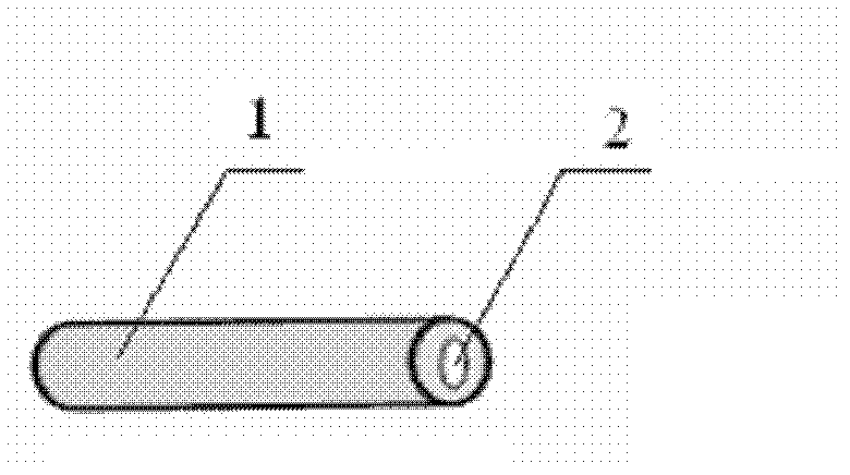
[0016] 2. Using a glass tube with a diameter of 0.2 mm to 5.0 mm as a template, assemble the polyelectrolyte layer into the hole of the template to obtain the skeleton of the microtube;

[0017] 3. Assembling the metal catalytic particles prepared in step 1 onto the skeleton of microtubules obtained in step 2 to obtain artificial microtubules.

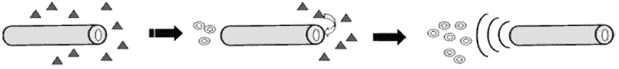
[0018] In this embodiment, platinum or silver micro-particles that catalyze hydrogen peroxide to decompose oxygen, templates for preparing microtubes, and artificial or natural polyelectrolytes for preparing microtubes are used as basic materials, and the polyelectrolyte microtubes and microtubes with Metal particles with catalytic performance are combined to prepare artificial microtubes. Put the artificial microtubes into ...

specific Embodiment approach 2

[0019] Specific embodiment 2: The difference between this embodiment and specific embodiment 1 is that the metal catalytic particles in step 1 are platinum particles with a particle size of 3nm to 100nm, silver particles with a particle size of 3nm to 100nm, or platinum or silver particles as the core Microparticles coated with citric acid or polydimethyldiallylammonium chloride with a particle size of 3nm to 100nm. Others are the same as in the first embodiment.

specific Embodiment approach 3

[0020] Embodiment 3: This embodiment differs from Embodiment 1 or Embodiment 2 in that the diameter of the glass tube in step 2 is 0.5 mm to 2.0 mm. Others are the same as in the first or second embodiment.

[0021] The glass tube of this embodiment is prepared by drawing.


PUM

PropertyMeasurementUnit
Particle sizeaaaaaaaaaa
Diameteraaaaaaaaaa

Abstract

The invention relates to a preparation method of an artificial microtube and the application of the artificial microtube as a micromotor. The invention relates to the preparation method and the application of the artificial microtube and solves the technical problems of high cost, small one-time synthetic quantity and large difficulty of the operation requirement of a particle beam injection method in the existing electrochemical deposition method for synthesizing a micro nano motor. The method comprises the steps of: preparing metal catalytic particles, assembling polyelectrolyte into the holes of a template layer by layer and assembling the metal catalytic particles to obtain the artificial microtube. For the application of the artificial microtube as the micromotor, the artificial microtube is put into a hydrogen peroxide solution, oxygen is generated via catalyzing hydrogen peroxide, and bubbles are used as impetus to drive the motor. The method is easy to operate, controllable in sizes, low in cost and large in one-time synthetic quantity. The artificial microtube provided by the invention can be used as the micromotor in the medical field.

Description

technical field [0001] The invention relates to a preparation method and application of microtubes. Background technique [0002] Artificial micron-scale motors are a hot area of ​​nanoscience in recent years. Micro-nano motors are micro-nano devices that catalyze hydrogen peroxide to generate oxygen and use bubbles to propel themselves forward, so that they can swim in a solution containing hydrogen peroxide. . The existing nanomotor synthesis methods include electrochemical deposition and particle beam spraying. However, the cost of micro-nanotubes synthesized by electrochemical deposition is expensive, and it is difficult to synthesize extremely small motors, and the number of synthesis at one time is small; the operation requirements of particle beam spraying are difficult, and only spherical motors can be prepared, and tubular motors cannot be prepared. Contents of the invention [0003] The present invention aims to solve the technical problems of high cost and rel...

Claims


Application Information

Patent Timeline
IPC IPC(8): B81C99/00F03H99/00
Inventor 贺强吴志光李薇薇
Owner HARBIN INST OF TECH
Why Eureka
Try Eureka