
Method of forming laser cladding layer on surface of upright post of hydraulic bracket

A technology of laser cladding and hydraulic support, which is applied in the direction of laser welding equipment, coating, metal material coating process, etc., to achieve the effect of efficient cladding

Active Publication Date: 2012-09-19
SHANDONG ENERGY HEAVY EQUIP GRP DAZU REMANUFACTURING CO LTD
View PDF4 Cites 11 Cited by
  • Summary
  • Abstract
  • Description
  • Claims
  • Application Information

AI Technical Summary

Problems solved by technology

[0005] For the laser cladding method of the above-mentioned mine hydraulic support column, although the formula of the alloy powder for laser cladding and the general process of the laser cladding method are described, the details of the laser cladding method still need to be refined place

Method used


Image

  • Method of forming laser cladding layer on surface of upright post of hydraulic bracket
  • Method of forming laser cladding layer on surface of upright post of hydraulic bracket
  • Method of forming laser cladding layer on surface of upright post of hydraulic bracket

Examples


Embodiment approach

[0106]In addition to the above first embodiment, the present invention also provides a second embodiment, the difference between the second embodiment and the first embodiment is that the n-1th laser cladding tape 5, the nth laser cladding The extension direction of the cladding strip 4 and the n+1th laser cladding strip 6 is not perpendicular to the axial direction of the hydraulic support column, but spirals around the outer surface of the hydraulic support column.

[0107] third implementation

[0108] In addition to the above first embodiment, the present invention also provides a third embodiment. The difference between the third embodiment and the first embodiment is that the alloy powder used for laser cladding contains 0.08% C, 0.9 % Si, 0.6% Mn, 18.5% Cr, 23% Ni, the balance Fe and unavoidable impurities. In this embodiment, since it contains more Ni, the cost is higher, and the Rockwell hardness is only above 30. Therefore, the effect of the third embodiment is not...


PUM


Abstract

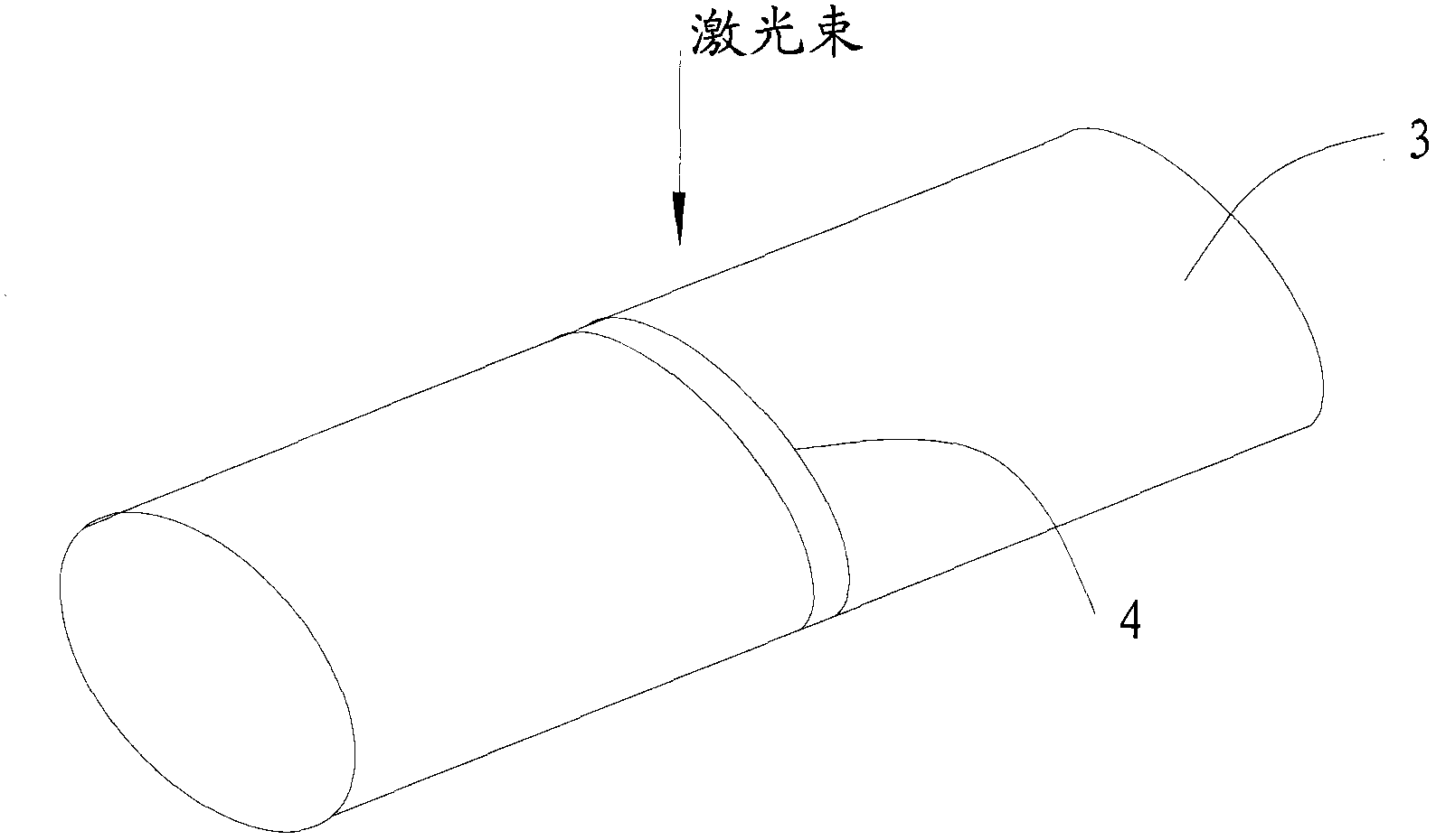
The invention provides a method of forming a laser cladding layer on the surface of an upright post of a hydraulic bracket. The method comprises the following steps of: step a). smelting a part of widths of (n-1)th laser cladding belt and laser cladding alloy powder used for forming the nth laser cladding belt through a laser beam to form the nth laser cladding belt, wherein n is an integer larger than or equal to 2; and step b). smelting a part of widths of the nth laser cladding belt and the laser cladding alloy powder used for forming (n+1)th laser cladding belt through the laser beam to form the (n+1)th laser cladding belt. The method provided by the invention can not only efficiently perform cladding, but also obtain a cladding surface with high strength.

Description

technical field [0001] The invention relates to a method for forming a laser cladding layer on the surface of a column of a hydraulic support, belonging to the field of laser processing and manufacturing. Background technique [0002] The hydraulic support column is a key component of mining equipment. In China, the hydraulic support column is usually treated with chrome plating to prevent surface rust and corrosion. However, the wear resistance of the chrome plating layer is poor. Generally, after 1 to 1.5 years, the chrome plating layer will appear peeling and peeling. Therefore, the emulsion will corrode the surface of the column, which will affect the use effect of the hydraulic support. [0003] The Chinese patent with the notification number CN101875128B discloses a laser cladding method for mining hydraulic support columns, which uses specific laser cladding process conditions to clap three layers of metallurgical materials, thereby solving the problem of the surface ...

Claims


Application Information

Patent Timeline
IPC IPC(8): C23C24/10B23K26/34
Inventor 李希勇李伦实周峰杜伯奇杨庆东苏伦昌董春春杨帆
Owner SHANDONG ENERGY HEAVY EQUIP GRP DAZU REMANUFACTURING CO LTD
Learn More