Low-carbon and environment-friendly distributed cooling system for engine and heat management method

A low-carbon, environmental-friendly, cooling system technology, applied to the cooling of the engine, engine components, machines/engines, etc., can solve the problems of not proposing the best working temperature method, not mentioning the influence of the engine and cooling pipeline, etc., to achieve Enhanced rapid maneuverability, enhanced heat radiation capability, and reduced energy consumption

Inactive Publication Date: 2012-09-19
SHANGHAI ZHONGFANG BAODA TEXTILE INTELLIGENT INSTR +2
View PDF3 Cites 7 Cited by
  • Summary
  • Abstract
  • Description
  • Claims
  • Application Information

AI Technical Summary

Problems solved by technology

The above invention patent applications are all based on the cooling system of the original engine. The difference from the original cooling system is only that the radiator in the original cooling system is replaced by heat pipes + cooling fins or oscillating flow heat pipes. Therefore, the improved cooling system There are still the same deficiencies as the original cooling system: low heat dissipation efficiency, high energy consumption, pollution of the environment by various coolant additives, damage or leakage of the cooling pipeline will affect the operation of the engine, etc.
However, the above-mentioned invention patent application neither mentioned how to ensure that the engine does not fail due to excessive heat dissipation during the cold start stage, nor did it propose a method to make the engine run at the optimum working temperature after normal operation

Method used


Image

  • Low-carbon and environment-friendly distributed cooling system for engine and heat management method
  • Low-carbon and environment-friendly distributed cooling system for engine and heat management method
  • Low-carbon and environment-friendly distributed cooling system for engine and heat management method

Examples


Embodiment Construction

[0029] Embodiments of the present invention will be further described below in conjunction with the accompanying drawings. However, those skilled in the art should recognize that the following implementations are only exemplary, and are intended to better enable those skilled in the art to understand the patent, and should not be construed as limiting the scope of the patent; as long as Any equivalent changes or modifications based on the spirit disclosed in this patent and similar structures, methods and similar changes thereof all fall within the scope of this patent.

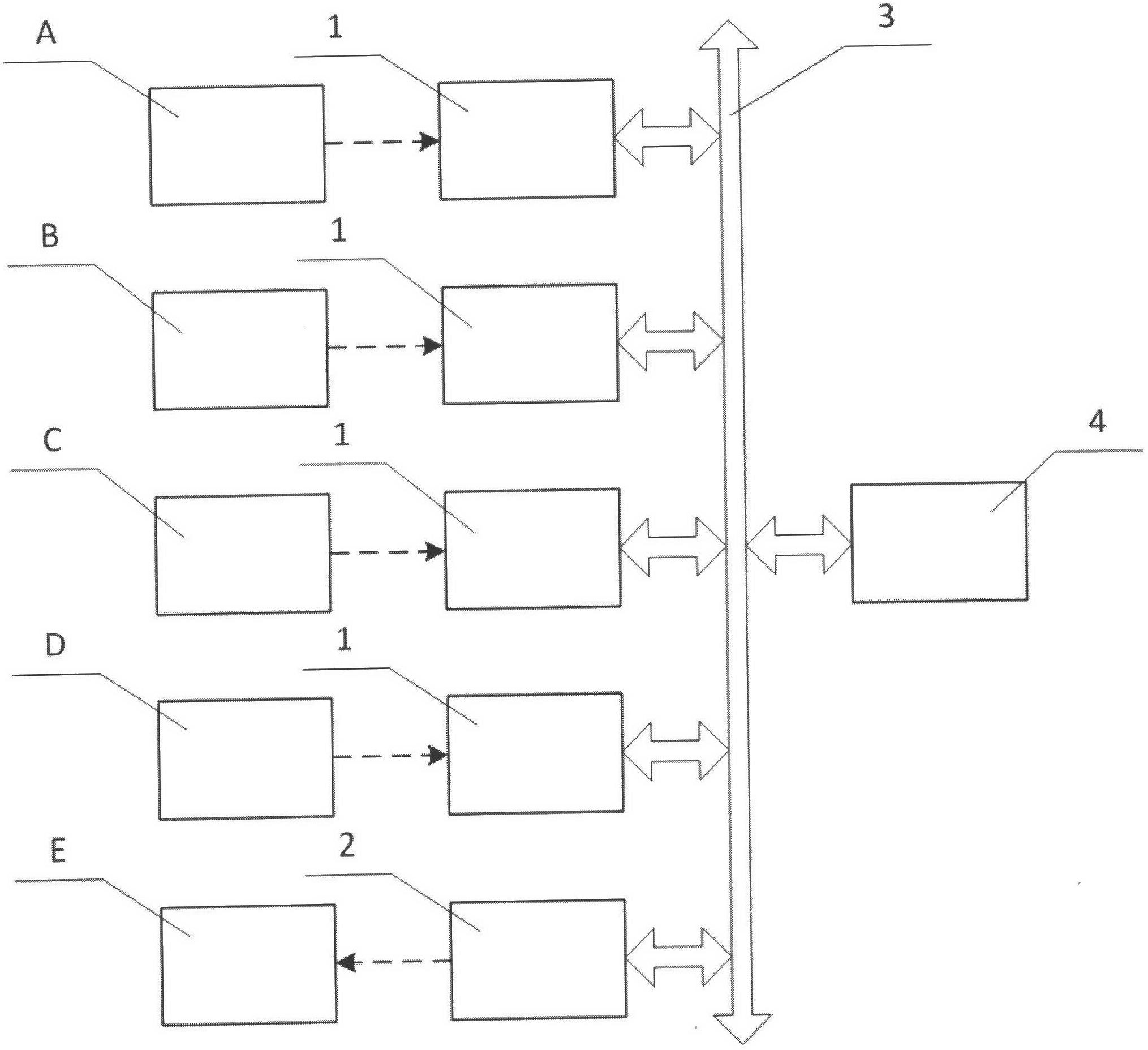
[0030] see figure 1 , the described a kind of low-carbon environment-friendly distributed cooling system for engine is made up of several sets of distributed cooling devices 1, cabin heating device 2, bus 3 and electronic control unit 4, respectively used to cool the cylinder head A of the engine , cylinder block B, pressurized air C and oil pan D, and heating for the compartment E.

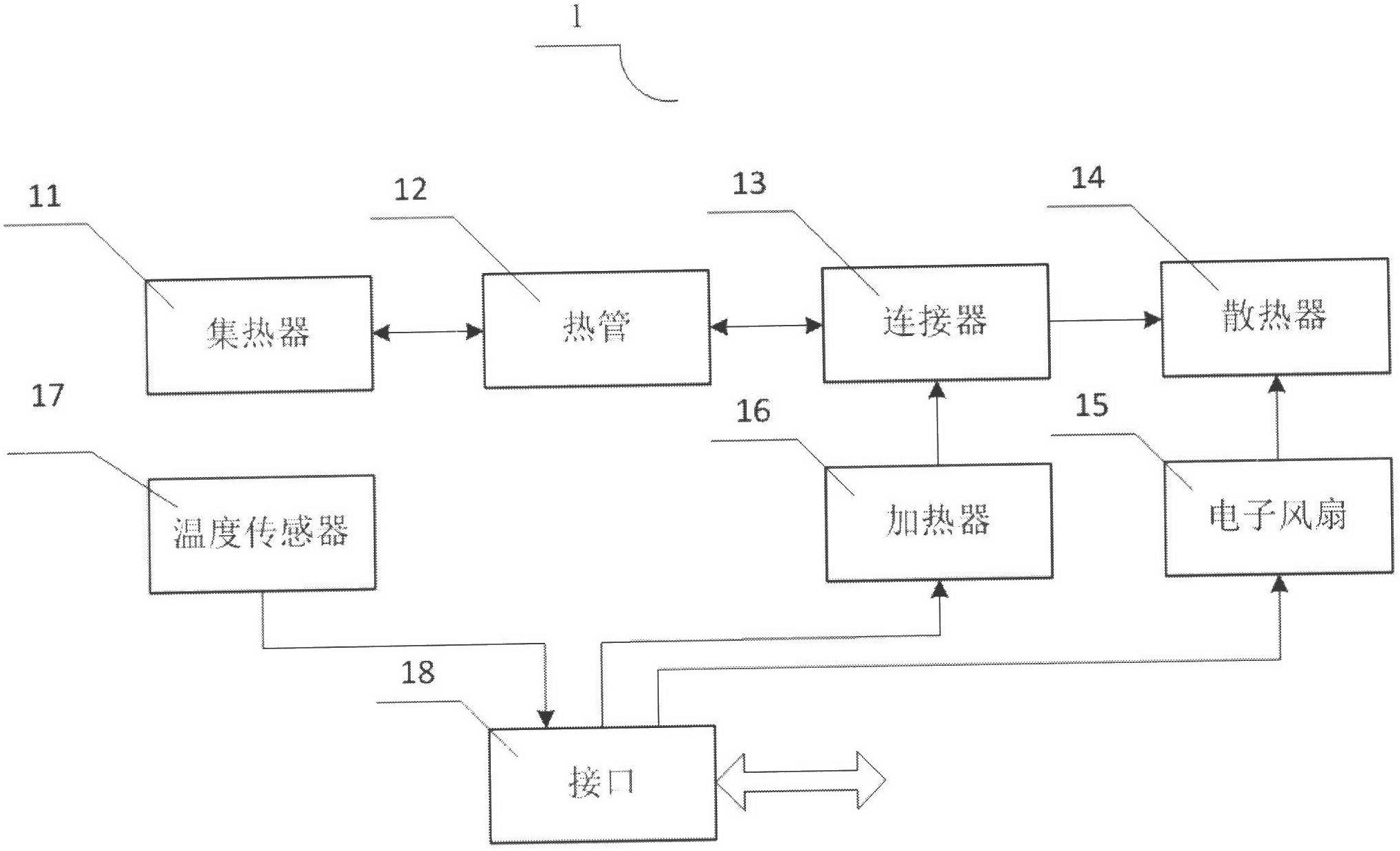
[0031] see figure 2 ...


PUM


Abstract

The invention discloses a low-carbon and environment-friendly distributed cooling system for an engine and a heat management method. The low-carbon and environment-friendly distributed cooling system for the engine comprises a plurality of sets of distributed cooling devices, a compartment heating device, a bus and an electronic control unit, wherein the distributed cooling devices are respectively used for cooling a cylinder cover, a cylinder body, pressurized air and an oilpan of the engine, and the compartment heating device is used for heating a compartment. Each set of distributed cooling device comprises a heat collector, one or more heat pipes, a connector, a heat radiator, an electronic fan, a heater, a temperature sensor and an interface; in the cold starting stage of the engine, the electronic fan is closed by an electronic control unit, the heater is started, and the cooled parts are preheated by utilizing the two-way heat-transfer characters of the heat pipes, so that the time consumed for cold starting is shortened, and the engine is enabled to rapidly enter a working state; and after the engine normally runs, the heater is closed by the electronic control unit, and the electronic fan is started, so that the distributed cooling devices are changed into a cooling working state. The low-carbon and environment-friendly distributed cooling system is particularly suitable for military or para-military application occasions requiring high response speed and high reliability.

Description

Technical field: [0001] The invention relates to the technical field of heat pipes, to the technical field of thermal management, and to the technical field of infrared, in particular to a low-carbon and environmentally friendly distributed cooling system and thermal management method for engines. Background technique: [0002] With the rapid development of social economy, the use of transportation means such as airplanes, automobiles, internal combustion engine trains, and ships is becoming more and more common. As the core component of various vehicles, the power per unit volume of the engine is continuously increasing, and the structure is becoming more compact. At the same time, the heat flux generated by the engine is also significantly increasing. At present, almost all engine enhancements are faced with how to solve the cooling problem under high power density, and have good economy while satisfying the continuously increasing output power. In addition, increasingly ...

Claims


Application Information

Patent Timeline
Patent Type & Authority Applications(China)
IPC IPC(8): F01P5/02F01P7/04B60H1/16F28D15/02
CPCY02T10/88
Inventor 孔繁金裘诚
Owner SHANGHAI ZHONGFANG BAODA TEXTILE INTELLIGENT INSTR
Why Eureka
Try Eureka