Fuel pump

A fuel pump, high-pressure fuel pump technology, applied in the direction of fuel injection pump, pump, fuel injection device, etc., can solve problems such as mechanical failure of pump piston fuel pump

Inactive Publication Date: 2012-09-19
MAN DIESEL & TURBO SE
View PDF7 Cites 0 Cited by
  • Summary
  • Abstract
  • Description
  • Claims
  • Application Information

AI Technical Summary

Problems solved by technology

In addition, due to deformation and / or pre-damage of the hard steel (microcracks caused by heat treatment), for example, cracks or fractures can occur in the area of ​​the strut foot or piston foot, which can lead to overheating of the pump piston and thus of the fuel pump. early mechanical failure

Method used


Image

  • Fuel pump
  • Fuel pump

Examples


Embodiment Construction

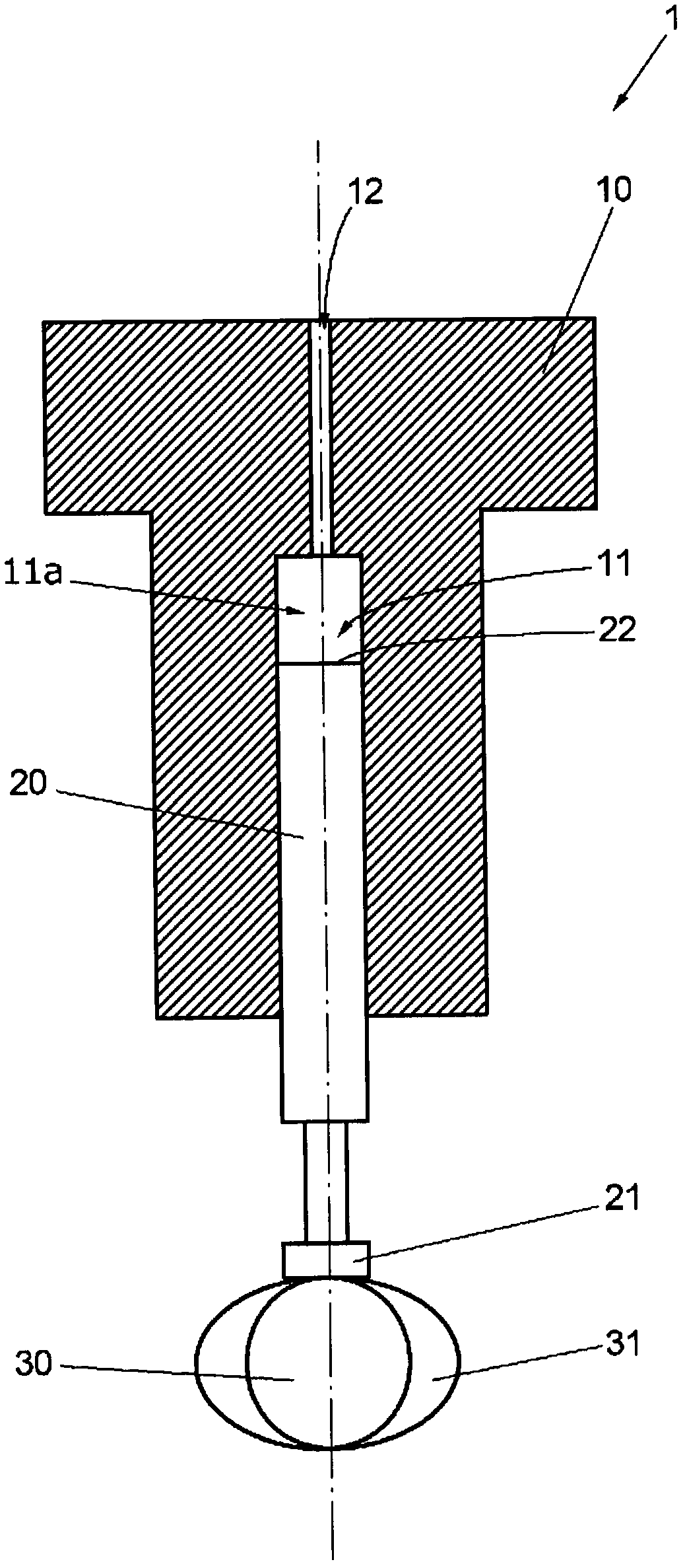
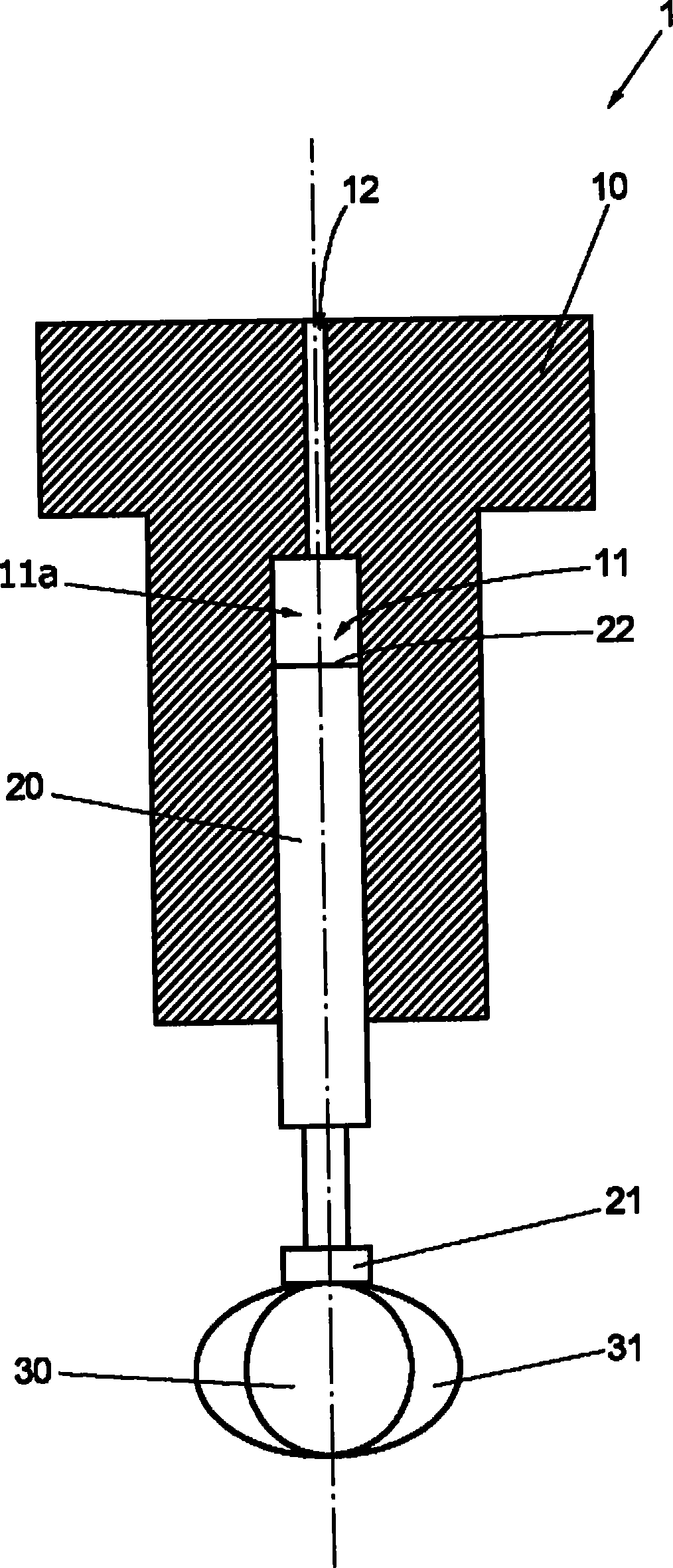
[0021] Such as figure 1 As shown, the fuel pump 1 according to the invention is here preferably configured as a high-pressure fuel pump (not completely shown) of a common rail fuel system, which has a pump cylinder 10 and a recess 11 in the pump cylinder 10 that can The movably mounted or guided pump piston 20 .

[0022] The pump piston 20 is controlled by at least one cam 31 arranged on a rotationally driven shaft 30 so as to be movable up and down in the pump cylinder 10 , wherein the fuel is moved down by the pump piston 20 through the fuel formed in the pump cylinder 10 The channel 12 is sucked into the area not occupied by the pump piston 20 or the pump chamber 11a of the recess 11 of the pump cylinder 10, and the sucked fuel is moved upward by the pump piston 20, passing through the fuel channel 12 and the not shown intermediate The storage device (for example, a delivery line here) is fed to a consumer (not shown), for example an injection valve of a fuel system.

[0...


PUM


Abstract

The invention provides a fuel pump (1), especially a high-pressure fuel pump of a common rail fuel system. The fuel pump comprises a metal pump cylinder (10) and a metal pump piston (20) movably guided therein. The fuel pump is manufactured by a manufacture technology with lower cost. Moreover, the pump piston (20) is made of a support material without heat treatment and coatings, wherein the support material is formed by a plastic alloy or a copper alloy.

Description

technical field [0001] The invention relates to a fuel pump according to the preamble of claim 1 . Background technique [0002] A fuel pump of the aforementioned type is known, for example, from document DE 60 202 042 T2. [0003] The fuel pump has a pump cylinder in which a pump piston is movably mounted or guided. The pump piston is moved up and down in the pump cylinder by means of one or more cams, whereby fuel is sucked in and, if necessary, delivered by the fuel pump via an intermediate storage device (such as a delivery line) to a consumer, such as for example an injection valve of a fuel system. [0004] Further details of high-pressure fuel pumps for fuel pumps, in particular for common rail fuel systems, are described in detail, for example, in DE 103 45 061 A1. [0005] Pump pistons made of steel, such as those described in DE 602 02 042 T2, are usually hardened and, if necessary, coated with an extremely complex production process in order to achieve self-lubr...

Claims


Application Information

Patent Timeline
Patent Type & Authority Applications(China)
IPC IPC(8): F02M59/02F02M59/44
CPCF04B1/0408F02M63/0265F02M59/445F02M59/02F04B53/14F05C2201/021F02M59/44F05C2201/0475F02M59/10C22F1/08
Inventor D·科瓦勒夫T·哈曼S·柯恩
Owner MAN DIESEL & TURBO SE
Why Eureka
Try Eureka