
Dew point indirect evaporation cooler with plate-tube combined structure

An evaporative cooler and dew point indirect technology, which is applied in the field of indirect evaporative coolers and dew point indirect evaporative coolers, can solve the problems of poor heat transfer effect, reduced efficiency, and limited temperature drop, so as to improve heat transfer efficiency and improve cooling Efficiency, Enhanced Uniformity Effect

Inactive Publication Date: 2012-09-19
XI'AN POLYTECHNIC UNIVERSITY
View PDF10 Cites 9 Cited by
  • Summary
  • Abstract
  • Description
  • Claims
  • Application Information

AI Technical Summary

Problems solved by technology

The plate-fin indirect evaporative cooler has the advantages of compact structure and high heat exchange efficiency. However, due to the narrow flow path of the heat exchanger, it causes high resistance and high energy consumption. Scale and air dust are easy to block the flow path of the heat exchanger. not easy to clean
The tubular indirect evaporative cooler is easy to form "dry spots" locally due to its tube shape, resulting in poor heat transfer effect and easy to form scale at the "dry spots".
In addition, only relying on indirect evaporative cooling for single-stage cooling, the temperature drop is limited, and the air temperature cannot approach its dew point temperature, resulting in reduced efficiency and affecting the air supply effect

Method used


Image

  • Dew point indirect evaporation cooler with plate-tube combined structure
  • Dew point indirect evaporation cooler with plate-tube combined structure
  • Dew point indirect evaporation cooler with plate-tube combined structure

Examples


Embodiment Construction

[0021] The present invention will be described in detail below in conjunction with the accompanying drawings and specific embodiments.

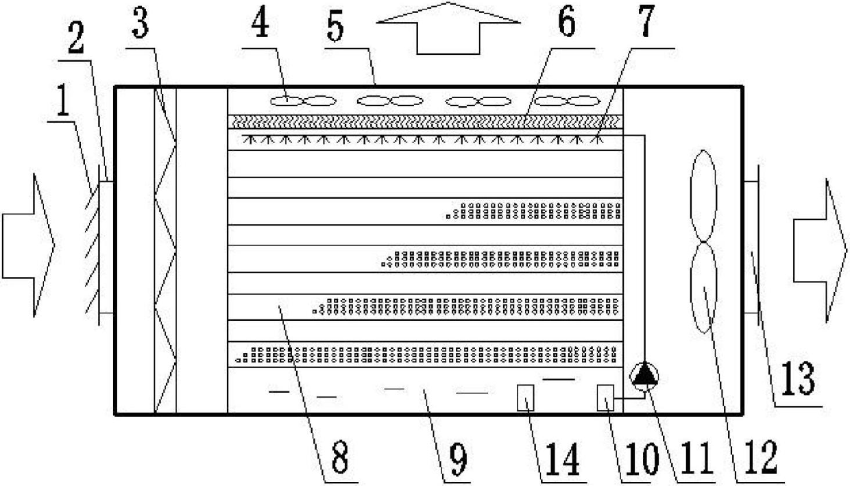
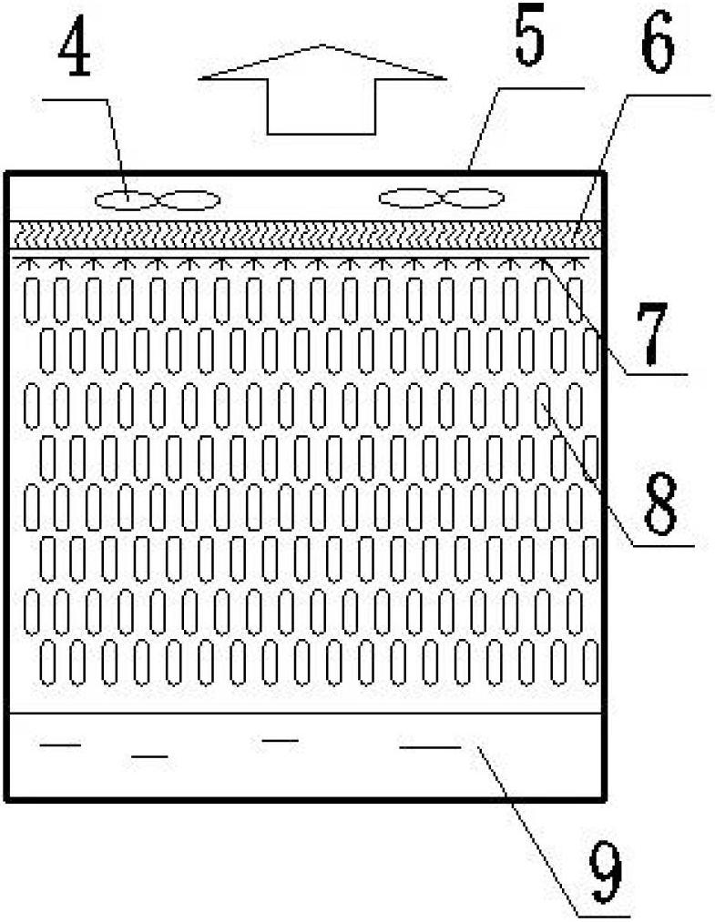
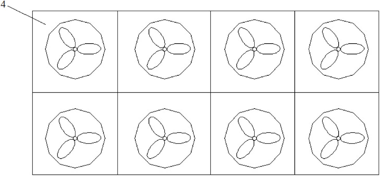
[0022] The evaporative cooler of the present invention has a structure such as figure 1 As shown, including the unit casing, air inlet 2 and air supply outlet 13 are respectively arranged on the opposite side walls of the unit casing, louvers 1 are arranged outside the air inlet 2, and louvers 1 are arranged in sequence according to the direction of air entering in the unit casing. The filter 3, the plate-and-tube heat exchanger 8 and the air blower 12, the water baffle 6 is arranged above the plate-and-tube heat exchanger 8, the multi-point fan device 4 is arranged above the water baffle 6, and the multi-point fan The unit casing corresponding to the device 4 is provided with an air outlet 5, and a spray branch pipe 7 for downward spraying is provided between the water baffle plate 6 and the plate-and-tube heat exchanger 8, and the bottom of...


PUM


Abstract

The invention discloses a dew point indirect evaporation cooler with a plate-tube combined structure. The dew point indirect evaporation cooler comprises a unit shell, wherein an air inlet and an air supply outlet which are respectively formed on the opposite side walls of the unit shell; the outer side of the air inlet is provided with a shutter; the unit shell is internally provided with a filter, a tube-on-sheet heat exchanger and an air feeder in sequence along the air inlet direction; a water baffle is arranged above the tube-on-sheet heat exchanger; a multi-point blower device is arranged above the water baffle; the part, corresponding to the multi-point blower device, of the unit shell is provided with an air outlet; a spray branch pipe is arranged between the water baffle and the tube-on-sheet heat exchanger; a water collection tank is arranged below the tube-on-sheet heat exchanger; the water collection tank is internally provided with a water replenishing valve and a water processor which is connected with the spray branch pipe through a waterway pipeline; and the waterway pipeline is provided with a water circulating pump. The evaporation cooler disclosed by the invention can be used for solving the problems of low heat exchange efficiency, large resistance and high scaling possibility existing in the application of an indirect evaporation cooler.

Description

technical field [0001] The invention belongs to the technical field of air-conditioning equipment, and relates to an indirect evaporative cooler, in particular to a dew-point indirect evaporative cooler with a plate-tube combination structure. Background technique [0002] Evaporative cooling air-conditioning technology is an environmentally friendly, efficient and economical cooling technology that uses water evaporation to absorb heat and refrigerate. The evaporative cooling process mainly uses water as the refrigerant. Since it does not use CFCs, it has no pollution to the atmospheric environment, and it can directly use fresh air, which greatly improves the indoor air quality. It is an energy-saving and environmentally friendly technology. This energy saving and environmental protection technology plays a very positive role in promoting energy saving and emission reduction. [0003] There are two basic forms of evaporative coolers: direct evaporative coolers and indirec...

Claims


Application Information

Patent Timeline
IPC IPC(8): F24F5/00F24F13/30
Inventor 黄翔孙哲周海东范坤
Owner XI'AN POLYTECHNIC UNIVERSITY
Learn More