Control method of low temperature refrigeration of rooftop air conditioning unit

A control method and air-conditioning unit technology, which is applied in heating and ventilation control systems, heating methods, space heating and ventilation, etc., can solve problems such as indoor temperature rise, compressor damage, and affecting the service life of the machine, and the method is simple to achieve easy effect

Active Publication Date: 2014-04-02
NINGBO AUX ELECTRIC
View PDF3 Cites 0 Cited by
  • Summary
  • Abstract
  • Description
  • Claims
  • Application Information

AI Technical Summary

Problems solved by technology

For example, places with large heat dissipation, such as computer rooms and forging workshops, require that the indoor and outdoor be separated, and the indoor ambient temperature should be kept at about 18-30°. When the indoor machines or equipment are running, they will continuously dissipate heat, resulting in indoor The temperature continues to rise, which affects the service life of the machine or affects the work efficiency of the workers. This requires the air conditioning unit to perform cooling operation even when the ambient temperature is low.
However, in the roof air conditioner of the prior art, in a low-temperature environment, the pressure of the high-temperature gas discharged from the compressor is low due to the low ambient temperature when the air-conditioning unit is running. The low evaporating pressure causes the evaporating temperature to be far lower than 0°, and when the evaporating temperature is lower than 0°, the condensed water on the evaporator will gradually turn into frost, thereby reducing the indoor air passing through the evaporator, causing the refrigerant to fail Enough heat exchange and complete evaporation into gas, carrying liquid into the compressor, causing the compressor to perform liquid compression will eventually cause the compressor to be damaged too quickly

Method used


Image

  • Control method of low temperature refrigeration of rooftop air conditioning unit
  • Control method of low temperature refrigeration of rooftop air conditioning unit

Examples


Embodiment Construction

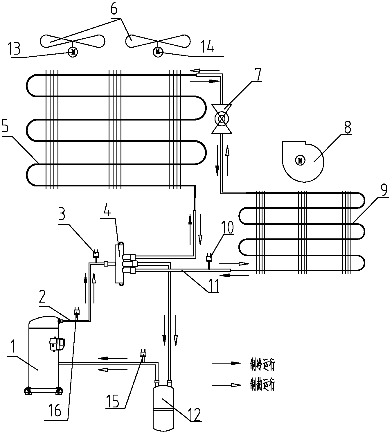
[0019] Below in conjunction with the accompanying drawings and specific embodiments, the low-temperature refrigeration control method of the patented rooftop air-conditioning unit will be further described in detail, but the present invention is not limited to the following specific embodiments: as shown in the attached figure 1 As shown, the schematic diagram of the air-conditioning unit system of the low-temperature refrigeration control method of the roof-type air-conditioning unit of the present invention, wherein the compressor 1, the exhaust pipe 2, the four-way reversing valve 4, the outdoor heat exchanger 5, the outdoor axial flow fan 6, and the throttling Device 7, indoor centrifugal fan 8, indoor heat exchanger 9, air return pipe 11, gas-liquid separator 12; first fan 13, second fan 14, low-voltage switch 15, high-voltage switch 16, forming a conventional roof air-conditioning unit in the industry, It will not be described in detail here; figure 1 The unit system dia...


PUM


Abstract

The invention discloses a control method of low temperature refrigeration of a rooftop air conditioning unit. The method includes the steps that a first mechanical pressure switch with an off value P1 and an on value P2 is additionally arranged on an exhaust pipe; a second mechanical pressure switch with an off value P3 and an on value P4 is additionally arranged on an air returning pipe; the unit performs refrigeration operation, and two fans operate simultaneously when a exhaust pressure value is larger than or equal to P2; when the exhaust pressure value is equal to or smaller than P1, the first mechanical pressure switch is off, and a first fan stops the service; when an air returning pressure value is equal to or smaller than P3, the second mechanical pressure switch is off, and an indoor fan stops the service; when the air returning pressure value is equal to or larger than P4, the second mechanical pressure switch is on, an alternating current contactor of a second fan pulls in, and the second fan operates alone. According to the control method of the low temperature refrigeration of the rooftop air conditioning unit, refrigerants which are not evaporated completely can be prevented from entering and damaging a compressor during the low temperature refrigeration operation.

Description

Technical field: [0001] The invention relates to the field of air conditioning, in particular to a low-temperature refrigeration control method for a roof-mounted air-conditioning unit with a three-phase fan. Background technique: [0002] Due to the large cooling capacity required by the existing roof air conditioner, the indoor and outdoor fan motors generally use a three-phase motor to drive the fan, which is basically composed of a compressor, a condenser, an outdoor dual-axial fan, a throttling device, and an evaporator. And indoor centrifugal fan composition. During cooling operation, the air conditioner unit transfers heat from the indoor to the outdoor through the work of the compressor according to the refrigeration principle. When the refrigerating cycle of the roof air-conditioning unit in the prior art is in normal operation, the outdoor biaxial fan, the indoor centrifugal fan, and the compressor are all in normal operation. [0003] At present, in the actual u...

Claims


Application Information

Patent Timeline
Patent Type & Authority Patents(China)
IPC IPC(8): F24F11/00
Inventor 郑坚江付冬金
Owner NINGBO AUX ELECTRIC
Why Eureka
Try Eureka