Check patentability & draft patents in minutes with Patsnap Eureka AI!

RC extraction for single-pattern spacings technology

A pattern and conductive pattern technology, applied in the field of semiconductor manufacturing, can solve problems such as intensive calculations

Active Publication Date: 2012-09-19
TAIWAN SEMICON MFG CO LTD
View PDF5 Cites 17 Cited by
  • Summary
  • Abstract
  • Description
  • Claims
  • Application Information

AI Technical Summary

Problems solved by technology

Although DPT has many advantages, its operation is relatively intensive

Method used


Image

  • RC extraction for single-pattern spacings technology
  • RC extraction for single-pattern spacings technology
  • RC extraction for single-pattern spacings technology

Examples


Embodiment Construction

[0040] The description of the exemplary embodiments is intended to be read in conjunction with the accompanying drawings, which are considered a part of the entire written description. In descriptions, relative terms such as "below", "above", "horizontal", "vertical", "above", "under", "upward" , "downward", "top" and "bottom" and their derivatives (such as "horizontally", "downwardly", "upwardly", etc.) shall refer to the directions described or shown in the views discussed below to explain. These relative terms are used for convenience of description and do not require a particular orientation in which the device is constructed or operated.

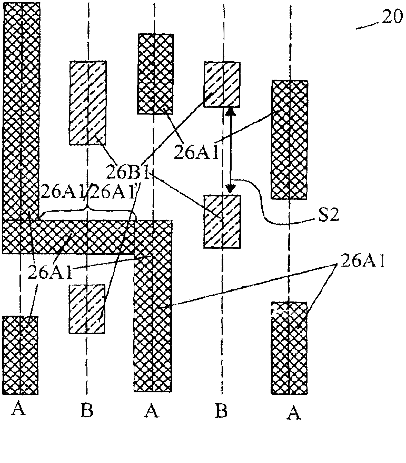
[0041] US Patent Application Serial No. 12 / 907,640, filed October 19, 2010, is hereby incorporated by reference. A double patterning technique utilizing Single-Patterning Spacer Technique (SPST) is described herein.

[0042] figure 1 A plurality of first patterns (A patterns) 26A1 and second patterns (B patterns) 26B1 formed by a pl...


PUM


Abstract

The present invention provides a method, comprising performing a layout and wiring operation by using an electronic design automation tool, in order to form an initial layout of a photo mask for forming a circuit pattern of a semiconductor device. The layout and wiring operation is specified by a wiring rule of multi single-pattern spacings technology (SPST). A virtual conductive fill pattern is simulated by an EDA tool of an RC extraction tool, so as to forecast the position and the size of the virtual conductive fill pattern to be added into the initial layout of the photo mask. Based on the initial layout and the simulated virtual conductive fill pattern, the RC time-series analysis of the circuit pattern is performed in the EDA tool.

Description

technical field [0001] The subject matter relates generally to semiconductor fabrication and, more specifically, to utilizing electronic design automation tools to fabricate small circuit geometries. Background technique [0002] In semiconductor manufacturing processes, the resolution of photoresist patterns begins to blur at a half-pitch of approximately 45 nanometers (nm). In order to continue to take advantage of manufacturing equipment purchased for larger technology nodes, double exposure methods have been developed. [0003] Double exposure involves patterning a single layer of the substrate using two different masks in succession on the same layer of the substrate. A set of first patterns is formed using a first mask. The patterns in the second mask are positioned so as to form second patterns interposed between the first patterns formed by the first mask. As a result, the minimum line spacing in the combined pattern can be reduced while maintaining better resolut...

Claims


Application Information

Patent Timeline
Patent Type & Authority Applications(China)
IPC IPC(8): G06F17/50
CPCG06F2217/84G03F1/144G06F17/5081G06F17/50G03F1/38G03F1/36G06F30/398G06F2119/12H01L27/0207G06F30/00
Inventor 黄正仪赵孝蜀郑仪侃
Owner TAIWAN SEMICON MFG CO LTD
Features
  • R&D
  • Intellectual Property
  • Life Sciences
  • Materials
  • Tech Scout
  • Unparalleled Data Quality
  • Higher Quality Content
  • 60% Fewer Hallucinations
Learn More