Method for manufacturing flat-plate fluorescent lamp

A manufacturing method and technology for fluorescent lamps, which are applied in the manufacture of discharge tubes/lamps, cold cathodes, electrode systems, etc., can solve the problems of cracked plates of fluorescent lamps, low air extraction efficiency, and small size of air injection ports, and can solve fatal problems. Defects, improve the pumping efficiency, improve the effect of vacuum

Inactive Publication Date: 2012-09-19
FUJIAN YDJ LIGHT
View PDF6 Cites 3 Cited by
  • Summary
  • Abstract
  • Description
  • Claims
  • Application Information

AI Technical Summary

Problems solved by technology

The disadvantages of method 1 are: a. The periphery of the fluorescent lamp is sealed before vacuum treatment except for the exhaust port, and the natural gap between the glass plates is deformed under the pressure generated by the vacuum treatment, resulting in cracks and damage to the fluorescent lamp during production and use. , affecting product quality and cost, b. The size of the gas injection port set on the glass plate is small, and the extraction efficiency is low, which affects production efficiency
Not only is the efficiency low, but the defect in its manufacturing process is that it uses the air extraction port or the air injection port to evacuate, and after the vacuum treatment, it is bonded and sealed to the air extraction port or the air injection port.
When the first substrate attachment is bonded to the second substrate attachment, the flatness of the glass plate material, the unevenness of the channel coating phosphor and other processes, cause a gap between the glass plates of the fluorescent lamp. This gap is in the back channel. During the vacuum treatment, because the periphery of the glass plate of the fluorescent lamp is bonded and fixed, the internal and external pressure generated by the vacuum causes some gaps in the glass plate of the fluorescent lamp to be eliminated to form deformation stress, which is likely to cause cracking of the fluorescent lamp product, and some gaps that cannot be eliminated cause leakage Gap, resulting in a short circuit in the discharge channel, seriously affecting product quality

Method used


Image

  • Method for manufacturing flat-plate fluorescent lamp
  • Method for manufacturing flat-plate fluorescent lamp
  • Method for manufacturing flat-plate fluorescent lamp

Examples


no. 1 example

[0034] A method for manufacturing a flat fluorescent lamp, comprising the steps of:

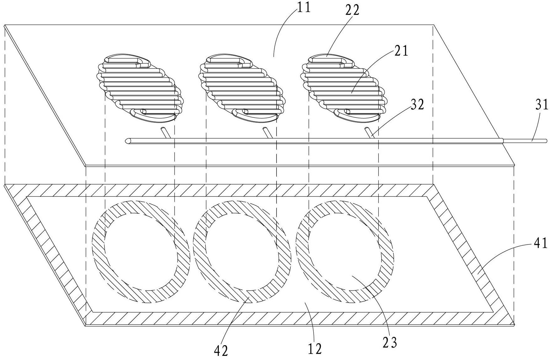
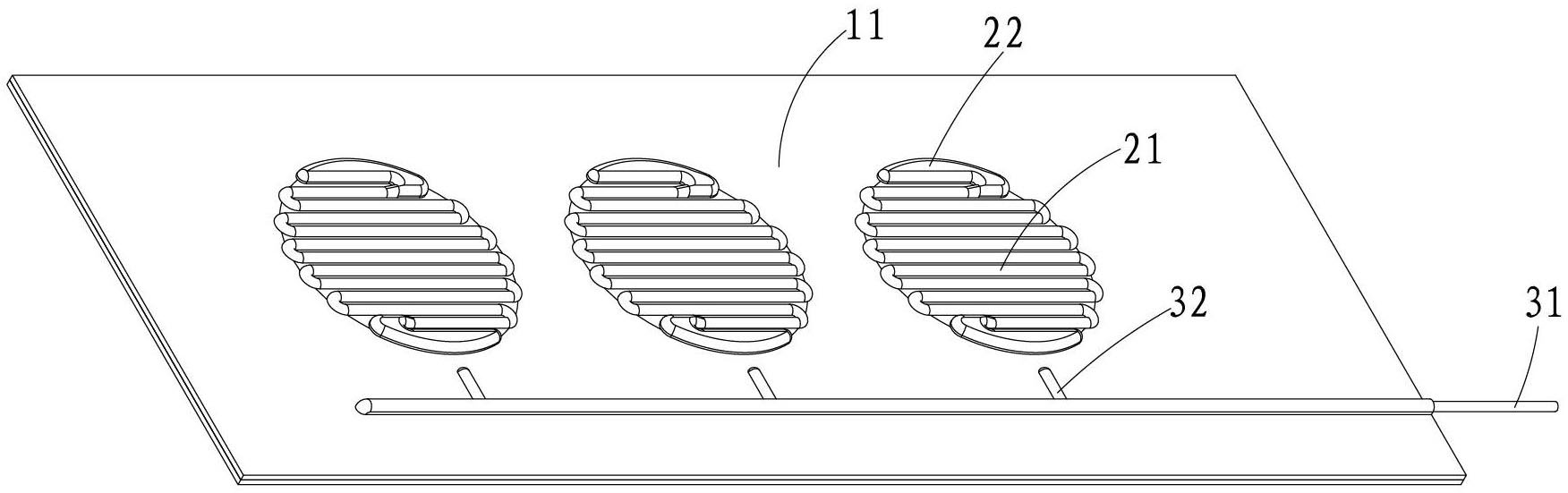
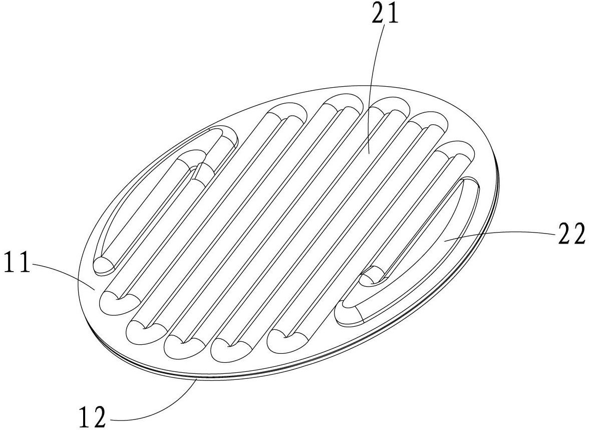
[0035] Step 1: If Figure 1A and Figure 1BAs shown, two glass plates are provided, a first glass plate 11 and an opposite second glass plate 12; wherein the first glass plate 11 is formed with discharge channels 21 and external electrodes 22 of three fluorescent lamps 20; on the first glass plate 11 An exhaust pipe 31 is provided at the edge of the first glass plate 11 , and an exhaust passage 32 is provided in the middle of the first glass plate 11 , and the exhaust passage 32 communicates with the exhaust pipe 31 .

[0036] Step 2: a first sealant 41 is provided on the periphery of the first glass plate 11 or the second glass plate 12, and a second sealant 42 is provided in the peripheral area 23 of the fluorescent lamp 20, wherein the melting point of the first sealant 41 is low at the melting point of the second sealant 42 .

[0037] Step 3: Attach the two glass plates 11, 12 together,...

no. 2 example

[0043] A method for manufacturing a flat fluorescent lamp, comprising the steps of:

[0044] Step 1: If Figure 2A As shown, two glass plates are provided, a first glass plate 11 and an opposite second glass plate 12; wherein the first glass plate 11 is formed with discharge channels 21 and external electrodes 22 of three fluorescent lamps 20, and the corresponding positions Discharge channels 21 and external electrodes 22 of three fluorescent lamps 20 are also formed on the second glass plate 12; an exhaust pipe 31 is arranged at the edge of the first glass plate 11, and an exhaust pipe 31 is also arranged in the middle of the first glass plate 11. A channel 32 , the exhaust channel 32 communicates with the exhaust pipe 31 .

[0045] Step 2: a first sealant 41 is provided on the periphery of the first glass plate 11 or the second glass plate 12, and a second sealant 42 is provided in the peripheral area 23 of the fluorescent lamp 20, wherein the melting point of the first se...

no. 3 example

[0052] The remaining steps of this embodiment are the same as those of the first embodiment, except that in step 1, spacers are placed between the two glass plates to form discharge channels, electrodes, and exhaust channels.

[0053] In the present invention, since the sealing around the discharge channel of the fluorescent lamp is completed once after the fluorescent lamp forms a vacuum environment, the two glass plates of the fluorescent lamp are squeezed by the huge pressure inside and outside the glass plate before sealing, eliminating the gap caused by the process or material, so that the sealing After the agent is sealed and sealed, there is no deformation stress between the glass plates of the fluorescent lamp, which solves the fatal defect of cracking the plates during the lighting process of the flat fluorescent lamp. At the same time, the gap between the discharge tubes is eliminated, the discharge resistance is increased, and the problem of the short circuit of the d...


PUM


Abstract

The invention relates to a method for manufacturing a flat-plate fluorescent lamp, comprising two fluorescent lamp glass plates, wherein a plurality of separable fluorescent lamp discharge channels and an electrode are arranged between two glass plates; a ring of sealant is arranged on at least one glass plate corresponding to the periphery of each fluorescent lamp; the peripheries of the two glass plates are firstly adhered so as to be sealed to form a cavity body; the cavity is vacuumized to form a vacuum environment; a gas discharge medium is injected into the vacuum environment; and in the vacuum environment, the sealant on the periphery of each fluorescent lamp is heated and molten, and each fluorescent lamp on the glass plate is cut and separated so that the plurality of flat-plate fluorescent lamps are obtained. Through the method for manufacturing the flat-plate fluorescent lamp, more fluorescent lamps are produced once, the production cost is reduced, materials are saved, the production efficiency is greatly improved, and the yield is increased.

Description

【Technical field】 [0001] The invention relates to a fluorescent lamp and a manufacturing method thereof, in particular to a manufacturing method of a flat fluorescent lamp. 【Background technique】 [0002] The structure of the flat fluorescent lamp is made of two glass plates, a discharge channel is set between the two glass plates, a phosphor luminescent material is set on the wall of the discharge channel, the discharge channel is filled with discharge gas medium and mercury, and the two ends of the discharge channel Electrodes are provided. A typical flat fluorescent lamp is: External Electrode Flat Fluorescent Lamp (EEFL for short), which is developed to be used as a backlight source for liquid crystal devices. The research and development of general lighting products is in the experimental stage. The technical difference between backlight and general lighting is: general lighting requires higher light efficiency and high luminous intensity per unit area. Compared with ...

Claims


Application Information

Patent Timeline
Patent Type & Authority Applications(China)
IPC IPC(8): H01J9/26H01J9/40
Inventor 赖勇清关福民
Owner FUJIAN YDJ LIGHT
Why Eureka
Try Eureka