

Gate valve
A technology of isolation valve and gas isolation, which is applied in the direction of rising valve, valve details, valve device, etc., and can solve problems such as rising pipe blockage and hindering heat conduction
- Summary
- Abstract
- Description
- Claims
- Application Information
AI Technical Summary
Problems solved by technology
Method used
Image

Examples
no. 1 Embodiment approach )
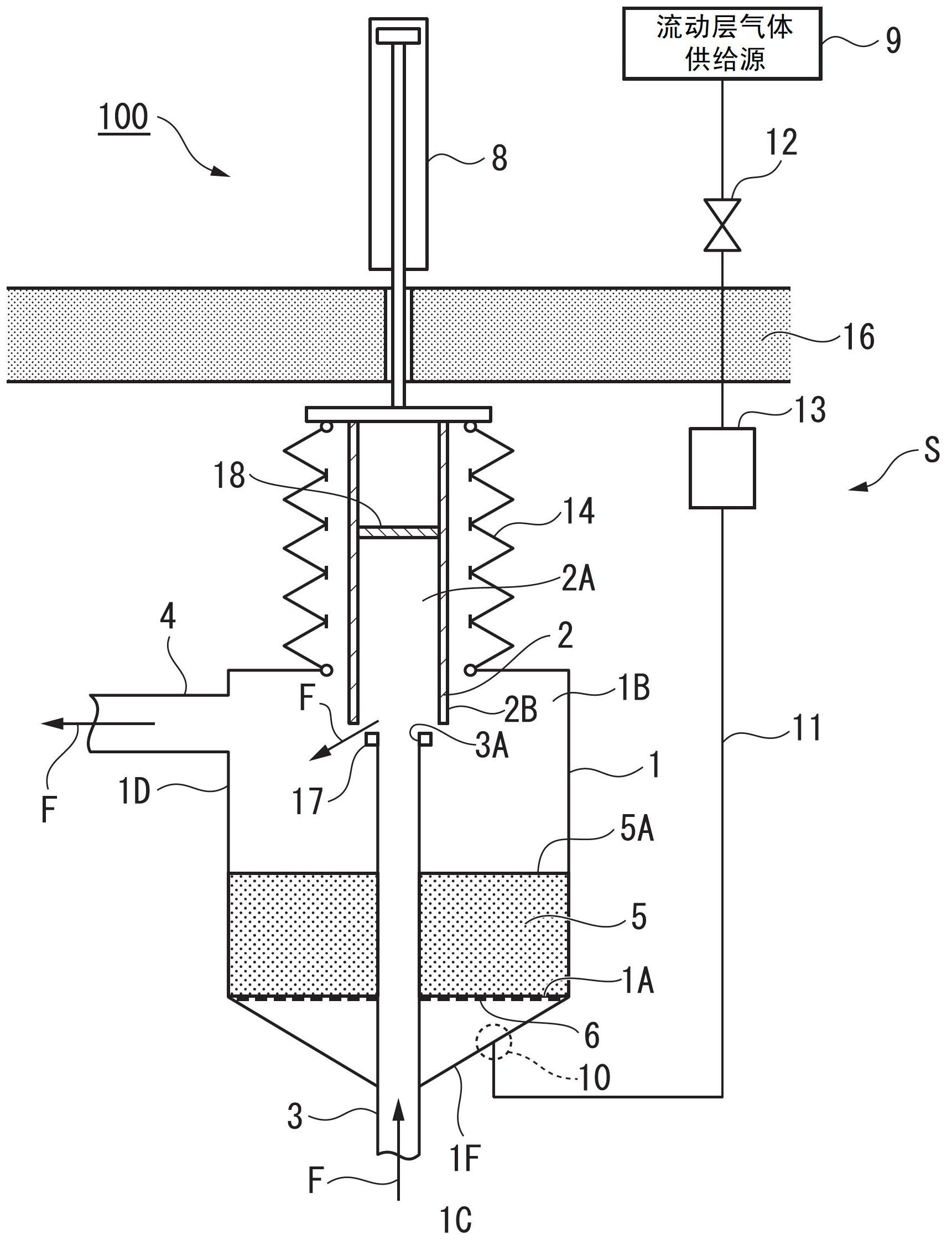
[0050] figure 1 represents the open state of the isolation valve 100, figure 2 The closed state of the isolation valve 100 is shown in . in addition, figure 1 The arrow F shown indicates the direction of flow of the working gas (such as gas components such as wet COG).
[0051] The isolation valve 100 described in this embodiment is a gas isolation valve for high-temperature furnace used in a high-temperature furnace. This high-temperature furnace gas isolation valve 100 includes: a granular sealing material 5 that can flow in a temperature range from normal temperature to 850°C or a temperature range of about 900°C; a valve box 1 that stores the sealing material 5 at the bottom 1A; Connected to box 1, high-temperature gas inflow pipe (first flow pipe) 3 that flows into high-temperature working gas (gas); connected to valve box 1, high-temperature gas outflow pipe (second flow pipe) 4 that flows out high-temperature working gas ; and the valve body 2 moving up and down. ...
no. 2 Embodiment approach )
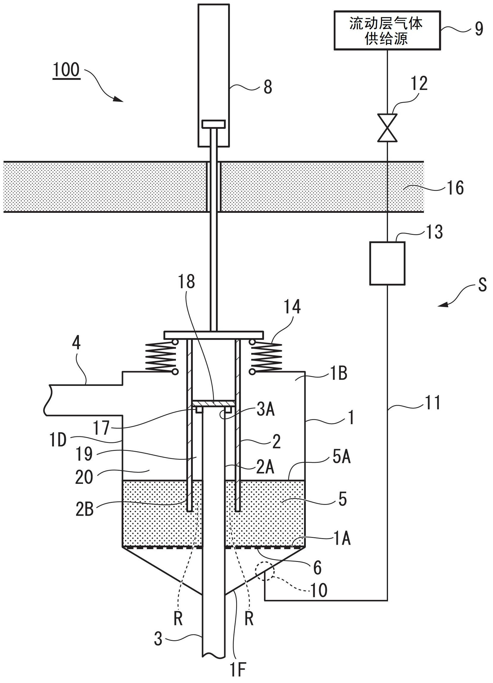
[0070] exist figure 2 In a state where the carbide is combusted as fluidized bed gas, gas capable of burning carbides is supplied to the valve box 1 from the fluidized bed gas inlet 10 through the fluidized bed gas pipe 11 . The fluidized bed gas passes through the sealing material 5 to burn and remove carbides mixed in the sealing material 5 . As a result of the combustion, generated gases such as carbon dioxide are discharged from the outflow pipe 4 to the outside of the valve together with the fluidized layer gas that has reached the upper surface of the sealing material 5 . In the present embodiment, since the fluidized bed gas is supplied in a state where the valve body 2 does not move in the sealing material 5 , it is not necessary to flow the sealing material 5 with the fluidized bed gas. Therefore, the supply amount of the fluidized bed gas can be set to be smaller than the flow rate at which the sealing material 5 flows. Thus, by adjusting the supply amount of the ...
no. 3 Embodiment approach )
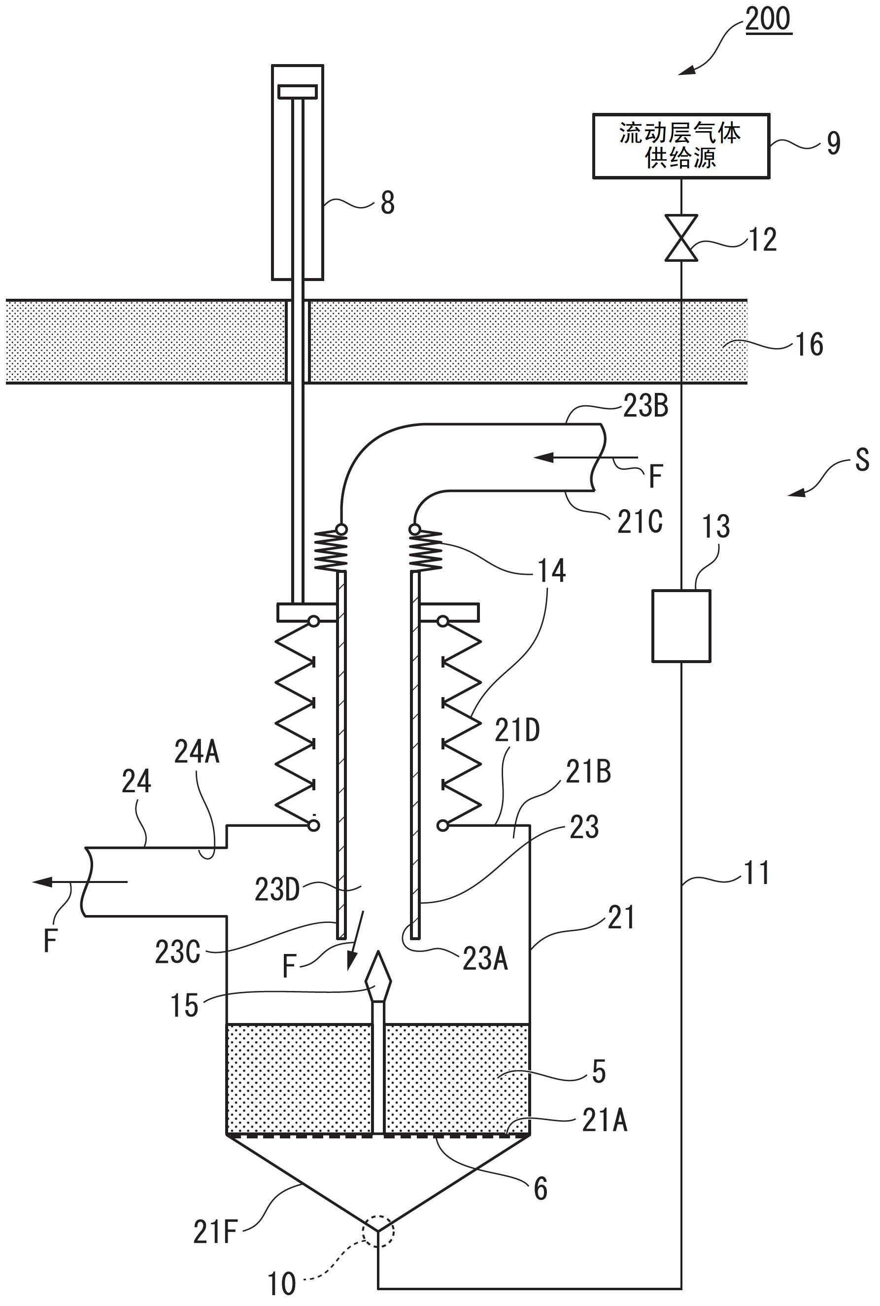
[0072] image 3 represents the open state of the isolation valve 200, Figure 4 The closed state of the isolation valve 200 is shown in . in addition, image 3 The arrow F shown indicates the flow direction of the working gas.
[0073] In this embodiment, a part of the high-temperature gas inflow pipe (first flow pipe) 23 is used as a valve body. Specifically, the high-temperature gas inflow pipe 23 extends from the upper part 21D of the valve box 21 toward the interior 21B of the valve box 21 and above the upper part 21D. The side is connected with the external 21C. With this configuration, the high-temperature working gas flows into the interior 21B of the valve box 21 from the lower end 23C through the upper end 23B of the high-temperature gas inflow pipe 23 .
[0074] When the isolation valve 200 is opened, the high-temperature working gas flows into the valve box 21 from the high-temperature gas inflow pipe 23 and flows out from the high-temperature gas outflow pipe ...
PUM
| Property | Measurement | Unit |
|---|---|---|
| Diameter | aaaaa | aaaaa |
| Layer thickness | aaaaa | aaaaa |
| Thickness | aaaaa | aaaaa |
Abstract
Description
Claims
Application Information