Bipolar secondary battery current collector
一种二次电池、双极型的技术,应用在二次电池、二次电池制造、电池电极等方向,能够解决输出功率降低、电池空间不利、电池输出功率密度、能量密度降低等问题,达到抑制电池温度的上升的效果
- Summary
- Abstract
- Description
- Claims
- Application Information
AI Technical Summary
Problems solved by technology
Method used
Image
Examples
Embodiment 1
[0104] As the conductive resin layer, a film having a thickness of 12.5 μm was prepared in which 5% by mass of Ketjen Black was added to 100% by mass of polyethylene. In addition, as an adhesive having conductivity, an adhesive A in which 20% by mass of carbon particles were added as a conductive material to heat-expandable microcapsules and whose viscosity was adjusted using xylene was prepared. In addition, this heat-expandable microcapsule is formed by encapsulating hexane as an expansion material in a polyvinyl chloride shell (particle diameter: 200 nm, melting point: 125° C.). The above-mentioned adhesive agent A is applied to one side of the above-mentioned resin layer in a thickness of 2 μm, and one layer of the above-mentioned resin layer is laminated on it and bonded to form a resin layer / adhesive layer / resin layer. formed current collectors.
[0105] The positive electrode active material slurry was applied to one surface of the obtained current collector, dried, an...
Embodiment 2
[0107] As the conductive resin layer, a film having a thickness of 25 μm was prepared in which 5% by mass of Ketjen Black was added to 100% by mass of polyethylene. The above-mentioned adhesive A was applied to one side of the above-mentioned resin layer so as to have a thickness of 2 μm, and dried to prepare a current collector composed of a resin layer / adhesive layer.
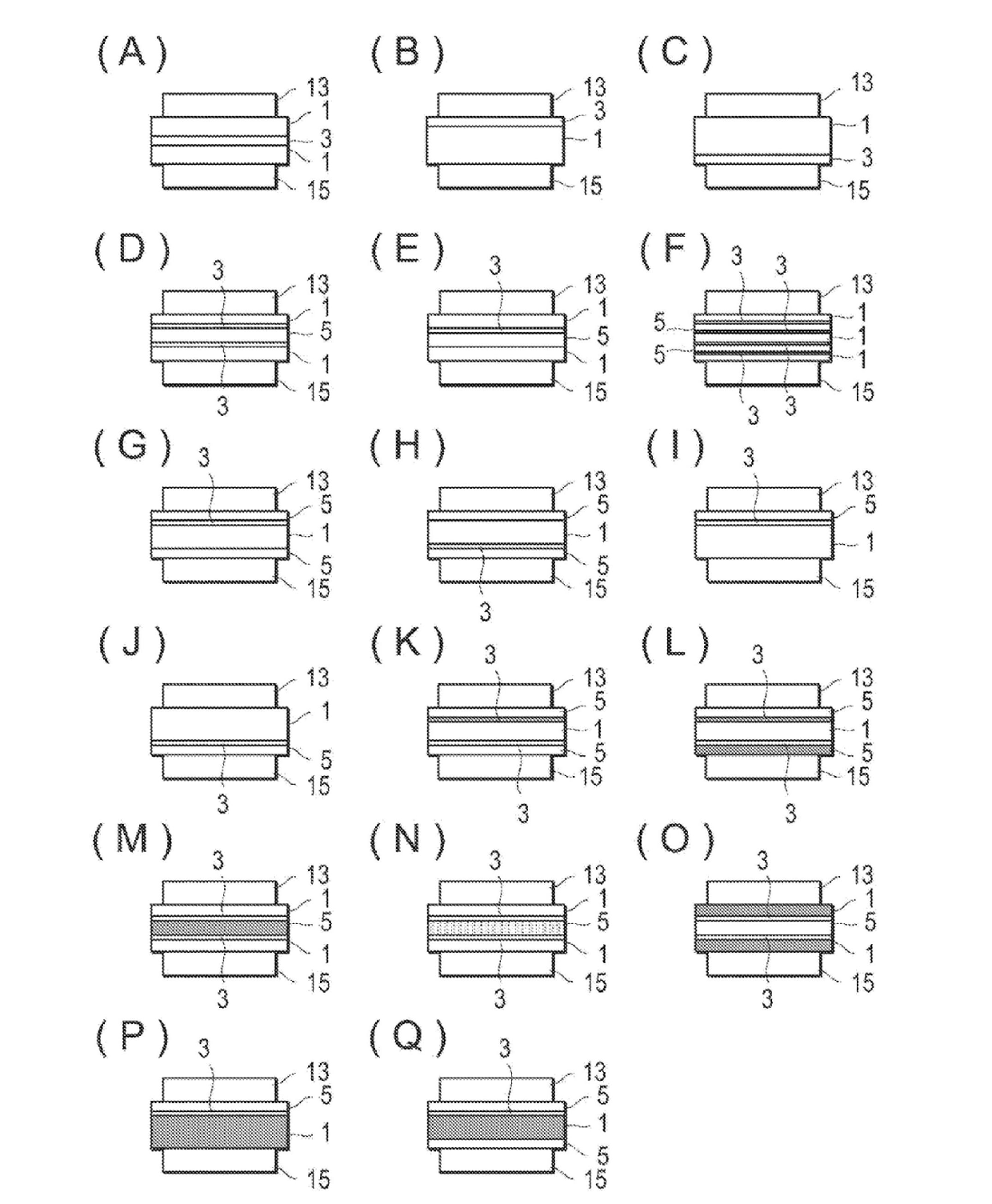
[0108] The positive electrode active material slurry was applied to the surface of the obtained current collector on the side of the adhesive layer, dried, and then pressed to form a positive electrode active material layer with a thickness of 36 μm. In addition, the above-mentioned negative electrode active material slurry was applied to the surface of the current collector on the resin layer side, dried, and then pressed to form a negative electrode active material layer with a thickness of 30 μm, thereby completing the bipolar electrode ( image 3 (B)).
Embodiment 3
[0110] As the conductive resin layer, a film having a thickness of 25 μm was prepared in which 5% by mass of Ketjen Black was added to 100% by mass of polyethylene. The above-mentioned adhesive A was applied to one side of the above-mentioned resin layer so as to have a thickness of 2 μm, and dried to prepare a current collector composed of a resin layer / adhesive layer.
[0111] The positive electrode active material slurry was applied to the surface of the obtained current collector on the resin layer side, dried, and then pressed to form a positive electrode active material layer with a thickness of 36 μm. In addition, the above-mentioned negative electrode active material slurry was applied to the surface of the current collector on the side of the adhesive layer, dried, and then pressed to form a negative electrode active material layer with a thickness of 30 μm, thereby completing a bipolar electrode. ( image 3 (C)).
PUM
| Property | Measurement | Unit |
|---|---|---|
| particle diameter | aaaaa | aaaaa |
| particle diameter | aaaaa | aaaaa |
| melting point | aaaaa | aaaaa |
Abstract
Description
Claims
Application Information
 - R&D
- Intellectual Property
- Life Sciences
- Materials
- Tech Scout
- Unparalleled Data Quality
- Higher Quality Content
- 60% Fewer Hallucinations
Browse by: Latest US Patents, China's latest patents, Technical Efficacy Thesaurus, Application Domain, Technology Topic, Popular Technical Reports.
© 2025 PatSnap. All rights reserved.Legal|Privacy policy|Modern Slavery Act Transparency Statement|Sitemap|About US| Contact US: help@patsnap.com


