
Current source application system for electrical impedance tomography and realization method thereof

A technology of electrical impedance tomography and application system, applied in application, diagnosis, diagnostic recording/measurement, etc., can solve problems such as voltage distribution deviation, data distortion, imaging failure, etc., achieve current deviation reduction, ensure imaging quality, and avoid data lost effect

Inactive Publication Date: 2012-09-26
SEALAND TECH CHENGDU
View PDF1 Cites 2 Cited by
  • Summary
  • Abstract
  • Description
  • Claims
  • Application Information

AI Technical Summary

Problems solved by technology

[0005] The purpose of the present invention is to provide a current source application system applied to electrical impedance tomography and its implementation method, which solves the problem that the equivalent capacitance to ground existing on the current output channel of the AC constant current source in the prior art makes the injection into the imaging target The deviation between the current of the AC constant current source and the ideal output current of the AC constant current source will cause the voltage distribution on the imaging target to deviate from the voltage distribution in the ideal state, which will eventually lead to the distortion of the data collected by the acquisition system, and even cause the problem of imaging failure.

Method used


Image

  • Current source application system for electrical impedance tomography and realization method thereof
  • Current source application system for electrical impedance tomography and realization method thereof
  • Current source application system for electrical impedance tomography and realization method thereof

Examples


Embodiment 1

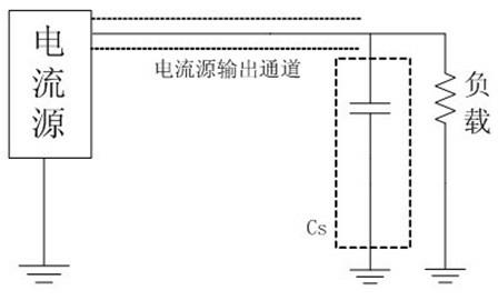
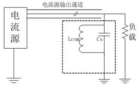
[0034] Such as figure 1 , 2 As shown, the current source application system applied to electrical impedance tomography includes a current source, and a load connected to the current source through a current source output channel, and the current source output channel has an equivalent ground connection in parallel with the load Capacitance C S , The equivalent capacitance to ground C S A compensation inductor L is also connected in parallel to reduce the deviation of the ideal output current injected into the imaging target body. com , And the equivalent capacitance to ground C S With compensation inductance L com The parallel equivalent impedance is: R eq =jωL com / (1-ω 2 L com C s ).

[0035] Wherein, the current source output channel is a current output cable; compensation inductance L com Select analog adjustable inductor; equivalent ground capacitance C S It is the sum of parasitic capacitance of electronic components, stray capacitance of circuit board traces, input / output ...

Embodiment 2

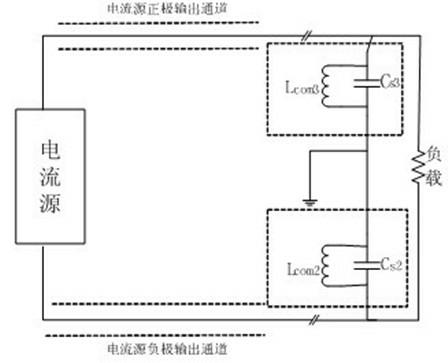
[0044] Such as image 3 As shown, the difference between this embodiment and Embodiment 1 is that in this embodiment, the current source is a bipolar current source, and its two ends are respectively connected to the load through a current source output channel, and each current source output channel All of the above have equivalent ground capacitances. In this embodiment, the two equivalent ground capacitances are respectively set as equivalent ground capacitances C S2 And equivalent ground capacitance C S3 , And correspondingly, set a compensation inductor for each equivalent ground capacitance: compensation inductor And compensation inductance

[0045] With the above settings, we will compensate the inductance Parallel to equivalent ground capacitance C S2 Both ends to achieve the current output channel to ground capacitance C S2 Compensation by adding the compensation inductance Parallel to equivalent ground capacitance C S2 Both ends to realize the current output channel t...

Embodiment 3

[0047] Such as Figure 4 As shown, the difference between this embodiment and Embodiment 1 is that in this embodiment, the current source is a single output frequency current source, the current source output channel is an electronic component through which the output current flows, and the equivalent ground capacitance exists in the output Correspondingly, we connect the compensation inductor in parallel with the two ends of the electronic component through which the output current flows to realize the equivalent ground capacitance compensation. In this embodiment, we choose the compensation circuit module as the compensation inductor. Compensate the equivalent capacitance to ground.

[0048] According to the equivalent ground capacitance C on the electronic component through which the output current flows S Measured data or evaluation data, combined with the output signal frequency f of the single output frequency current source in this embodiment, can roughly calculate the comp...


PUM


Abstract

The invention discloses a current source application system for electrical impedance tomography and a realization method thereof. The system comprises a current source and a load communicated with the current source through a current source output channel, wherein the current source output channel is provided with an equivalent ground capacitor CS connected in parallel with the load; the equivalent ground capacitor CS is also connected in parallel with a compensation inductor Lcom for reducing the deviation between the ideal output current and the current injected into an imaging target body; and the equivalent impedance of the parallel connection between the equivalent ground capacitor CS and the compensation inductor Lcom is: Req=j(omega)Lcom / (1-(omega)2LcomCS). Through the invention, the problems of the prior art that the equivalent ground capacitor on a current output channel of an AC (alternating current) constant-current source causes certain deviation between the current injected into the imaging target body and the ideal output current of the AC constant-current source and consequently leads to deviation between the voltage distribution on the imaging target body and the ideal status and finally causes distortion of the data acquired by an acquisition system and even causes imaging failure are solved; and the system and method disclosed by the invention have great practical values and application prospects.

Description

Technical field [0001] The invention relates to a current source application system, in particular to a current source application system applied to electrical impedance tomography and an implementation method thereof. Background technique [0002] Electrical impedance tomography is a non-destructive and harmless new imaging technology. It detects the impedance distribution inside the body under test by detecting the voltage difference between the electrodes, thereby reflecting the biological characteristics of each biological tissue in structure and function, and has a cost The advantages of low size, small size, sensitivity to early cancer foci, high data acquisition and imaging speed, etc., can be used for long-term real-time and dynamic monitoring of patients, and have broad medical applications. [0003] The factors that affect the quality of electrical impedance tomography include the stability of the hardware excitation source, the accuracy of the data acquisition system, an...

Claims


Application Information

Patent Timeline
Patent Type & Authority Applications(China)
IPC IPC(8): A61B5/053
Inventor 徐现红余华章戴涛吴梓敬费智胜
Owner SEALAND TECH CHENGDU
Learn More