
Novel three-point type bending machine hydraulic system with quick energy conservation

A hydraulic system and three-point technology, applied in the field of sheet metal bending machines, can solve problems such as inconvenience, large rebound of sheet metal, accident-prone maintenance, etc., and achieve the effect of convenient use and simple structure

Active Publication Date: 2012-09-26
重庆键英液压机电有限公司
View PDF10 Cites 12 Cited by
  • Summary
  • Abstract
  • Description
  • Claims
  • Application Information

AI Technical Summary

Problems solved by technology

[0003] Most of the current bending machines in our country adopt the V-shaped mold hollow bending method. This method is to change the bending angle by controlling the depth of the upper knife entering the V-shaped groove. The main disadvantages are: (1) The bending angle is not accurate ; ⑵The sheet material rebounds greatly; ⑶The stability of batch processing bending is poor; Based on the shortcomings of V-shaped bending, three-point bending effectively solves these problems. It can adjust the height of the lower mold core through 3-point positioning. Realize the bending of different angles of the sheet metal, the sheet material springback is small, and the bending angle is accurate and controllable
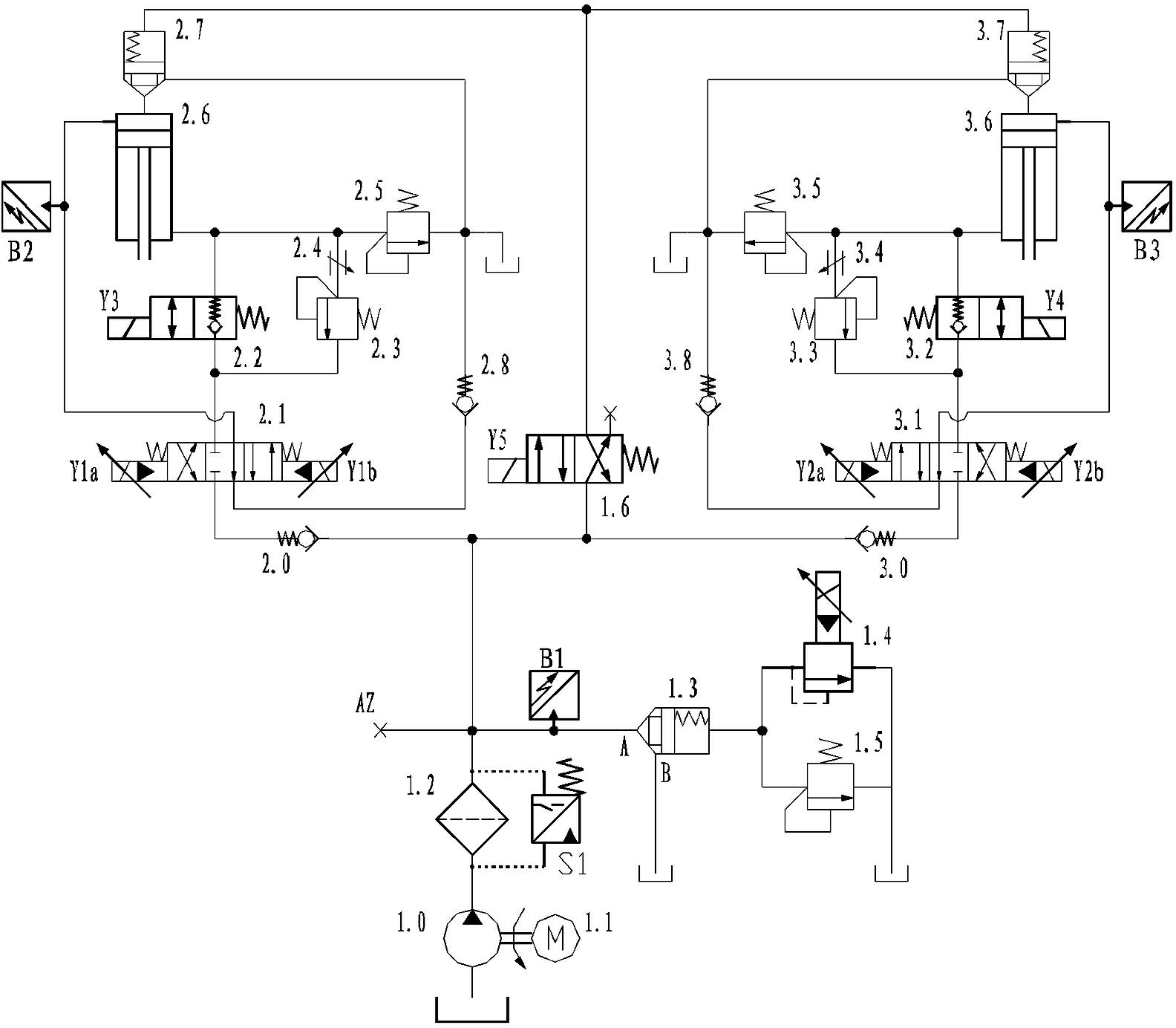
[0005] As mentioned above, the foreign three-point bending machine has the following disadvantages: (1) The main oil flow of the system is large, the motor power is high, and the energy consumption is large
If the flow rate of the main oil circuit is too large, a proportional relief valve group with a cartridge structure has to be used, which increases the failure rate of the system; (2) There are many types and quantities of hydraulic valves in the entire system, especially the performance requirements for proportional directional valves are high; (3) When the system is not working, the weight of the cutter board is supported by the sealing oil in the lower cavity of the oil cylinder, but there are many internal leakage points, which are prone to accidents and inconvenient maintenance

Method used


Image

  • Novel three-point type bending machine hydraulic system with quick energy conservation
  • Novel three-point type bending machine hydraulic system with quick energy conservation
  • Novel three-point type bending machine hydraulic system with quick energy conservation

Examples


Embodiment Construction

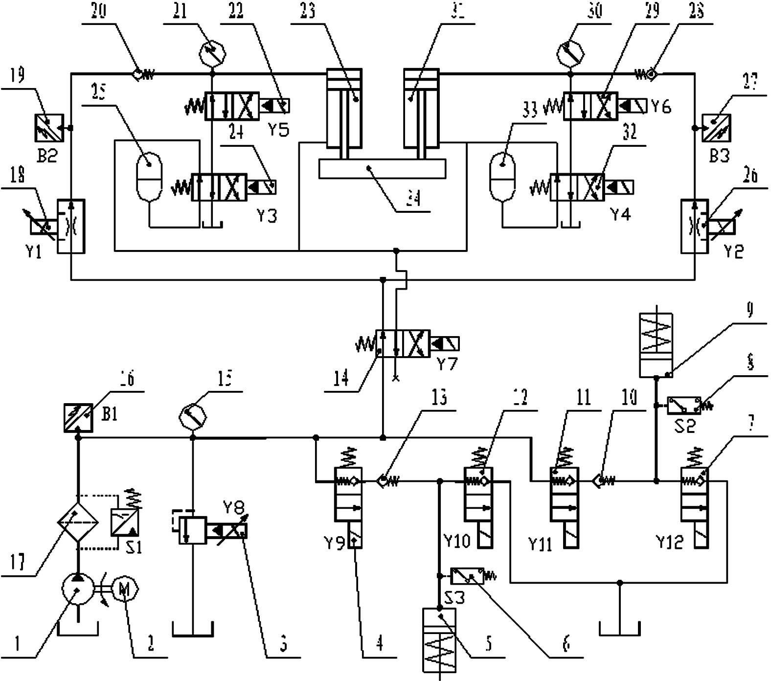
[0041] refer to figure 1 , the hydraulic system of the new fast and energy-saving three-point bending machine of the present invention includes a fuel tank, a power unit, a proportional overflow valve 3, a first reversing valve 14; a first proportional speed regulating valve 18, a first main oil cylinder 23, a first storage Energy control device, and the second proportional speed regulating valve 26, the second energy storage control device, the second master oil cylinder 31; and the upper knife plate 34; and the hydraulic clamping mechanism of the upper mold and the hydraulic clamping mechanism of the lower mold.

[0042] refer to figure 1 One end of the power unit is connected in parallel with one end of the proportional overflow valve 3 and then connected to the oil tank, and the other end of the power unit is connected in parallel with the other end of the proportional overflow valve 3 and then connected with the first reversing valve 14 . The power unit is composed of ...


PUM


Abstract

The invention discloses a novel three-point type bending machine hydraulic system with quick energy conservation. One end of a first proportion speed control valve is connected with a first oil port of a first reversing valve; one end of a first energy storage control device is connected in parallel with a rodless cavity of a first main oil cylinder and is connected with the other end of the first proportion speed control valve; the other end of the first energy storage control device is connected in parallel with a rod cavity of the first main oil cylinder and is connected with a second oil port of the first reversing valve; the first energy storage control device is also communicated with an oil tank; one end of a second proportion speed control valve is connected with the first oil port of the first reversing valve; one end of a second energy storage control device is connected in parallel with a rodless cavity of a second main oil cylinder and is connected with the other end of the second proportion speed control valve; the other end of the second energy storage control device is connected with a rod cavity of the second main oil cylinder and is connected with the second oil port of the first reversing valve; the second energy storage control device is also communicated with the oil tank; and the first main oil cylinder and the second main oil cylinder are connected with an upper cutting board at the same time. The novel three-point type bending machine hydraulic system with quick energy conservation has the advantages of simpleness, reliability, quick energy conservation and large tonnage.

Description

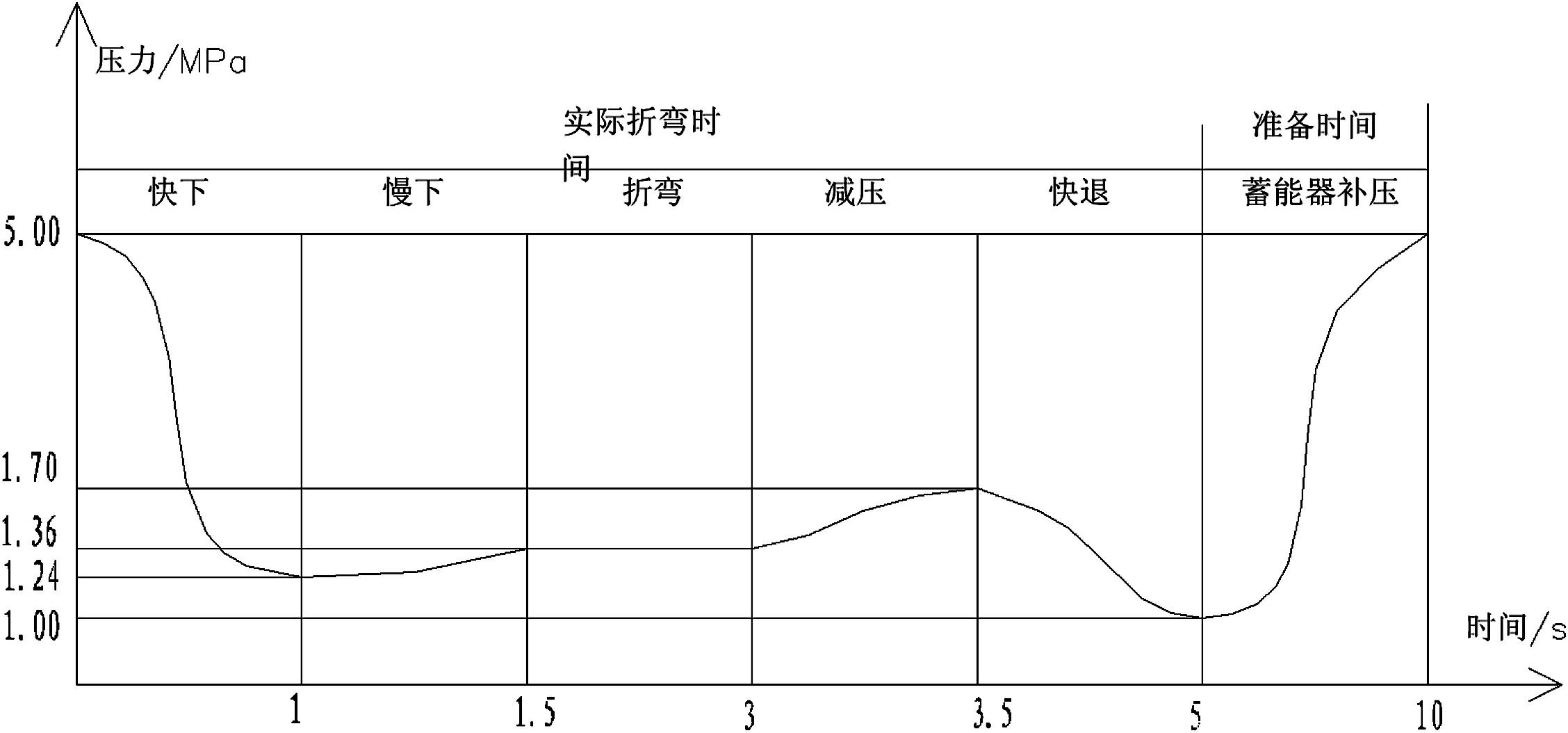
technical field [0001] The invention relates to the technical field of sheet metal bending machines, in particular to a novel fast and energy-saving three-point bending machine hydraulic system. Background technique [0002] The bending process of ordinary bending machine is mainly: fast down-slow down-bending-fast back. When the slider moves down quickly, because the speed is high and the instantaneous flow is large, it is necessary to choose a high-power motor or adopt a speed-increasing cylinder structure, but these two methods are not economical. [0003] Most of the current bending machines in our country adopt the V-shaped mold hollow bending method. This method is to change the bending angle by controlling the depth of the upper knife entering the V-shaped groove. The main disadvantages are: (1) The bending angle is not accurate ; ⑵The sheet material rebounds greatly; ⑶The stability of batch processing bending is poor; Based on the shortcomings of V-shaped bending, t...

Claims


Application Information

Patent Timeline
IPC IPC(8): F15B1/02F15B11/02B21D5/06
Inventor 李巧张勇
Owner 重庆键英液压机电有限公司
Learn More