
Laser detection method based on dense pulses

A dense pulse, laser detection technology, applied in the field of laser detection, can solve problems such as unfavorable long-distance detection of fast-moving targets, low signal-to-noise ratio, etc., to reduce detectable optical power, improve signal-to-noise ratio, and save detection time. Effect

Inactive Publication Date: 2012-09-26
TSINGHUA UNIV
View PDF7 Cites 22 Cited by
  • Summary
  • Abstract
  • Description
  • Claims
  • Application Information

AI Technical Summary

Problems solved by technology

[0011] To sum up, when the low-light detector is used for direct light detection, the signal-to-noise ratio is low due to the influence of environmental stray light; although the time-correlated detection technology of multi-pulse superposition or optical heterodyne detection method can improve the signal-to-noise ratio, Reduce the minimum detectable signal optical power, but the time-correlated detection technology of multi-pulse superposition is not conducive to long-distance detection of fast-moving targets because the time interval between adjacent detection laser pulses is too large, while the method of optical heterodyne detection is affected by the atmosphere. The impact of turbulence is greater. The high repetition frequency laser ranging technology used in artificial satellite laser ranging needs to know the calculated distance between the measured target and the measuring point in advance. If the distance of the measured target is not known in advance or the deviation between the calculated distance and the time distance If the value is large, the distance information of the target cannot be obtained by using this method, and the high repetition frequency laser detection pulse is continuously emitted, the time interval between adjacent detection pulses is equal, and the measured target is a cooperative target

Method used


Image

  • Laser detection method based on dense pulses
  • Laser detection method based on dense pulses
  • Laser detection method based on dense pulses

Examples


Embodiment Construction

[0036] The specific implementation manners of the present invention will be further described in detail below in conjunction with the accompanying drawings and embodiments. The following examples are used to illustrate the present invention, but are not intended to limit the scope of the present invention.

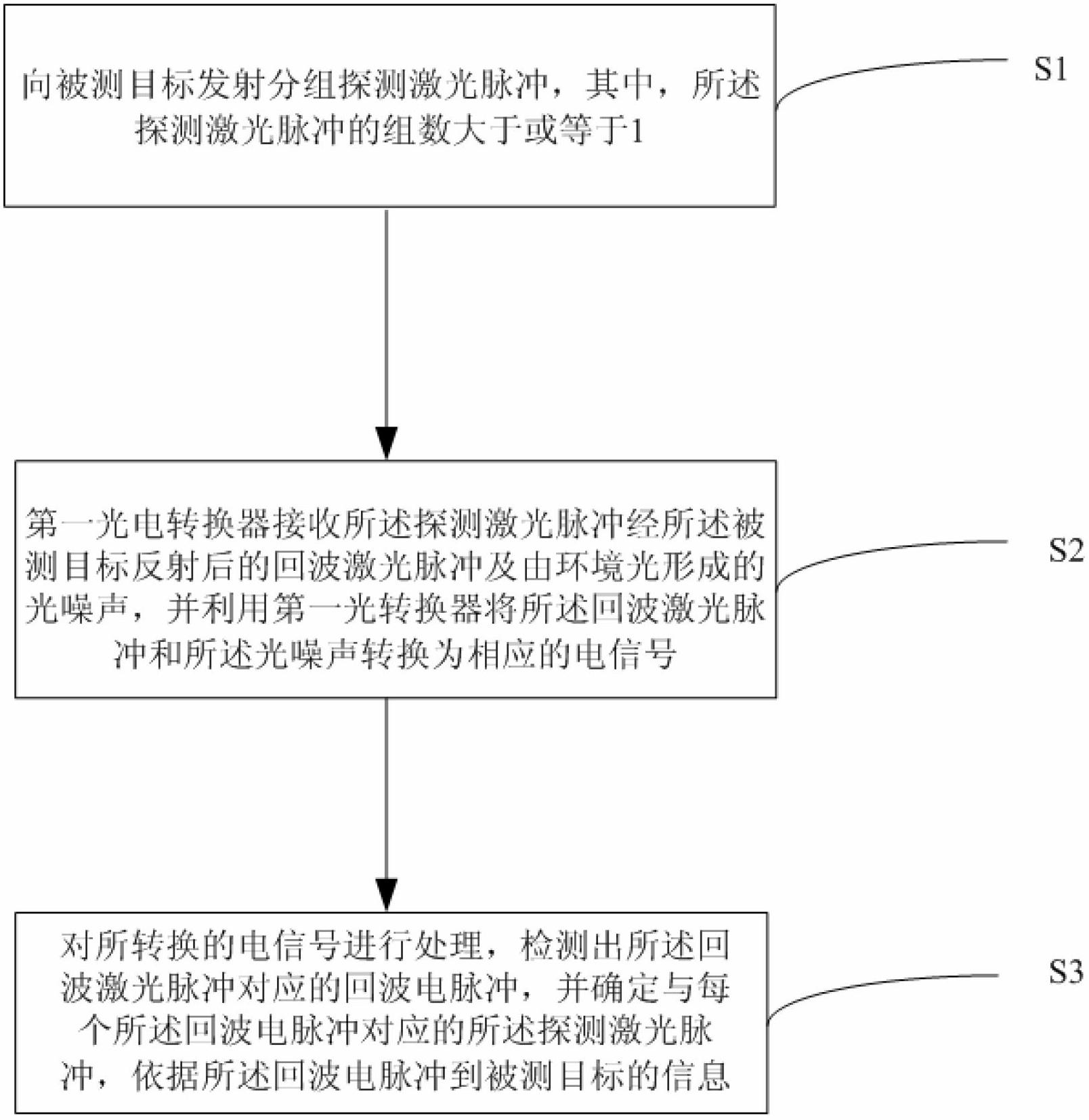
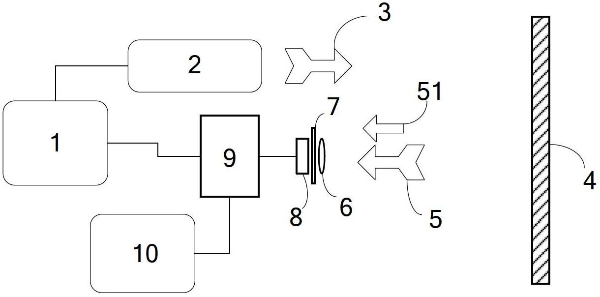
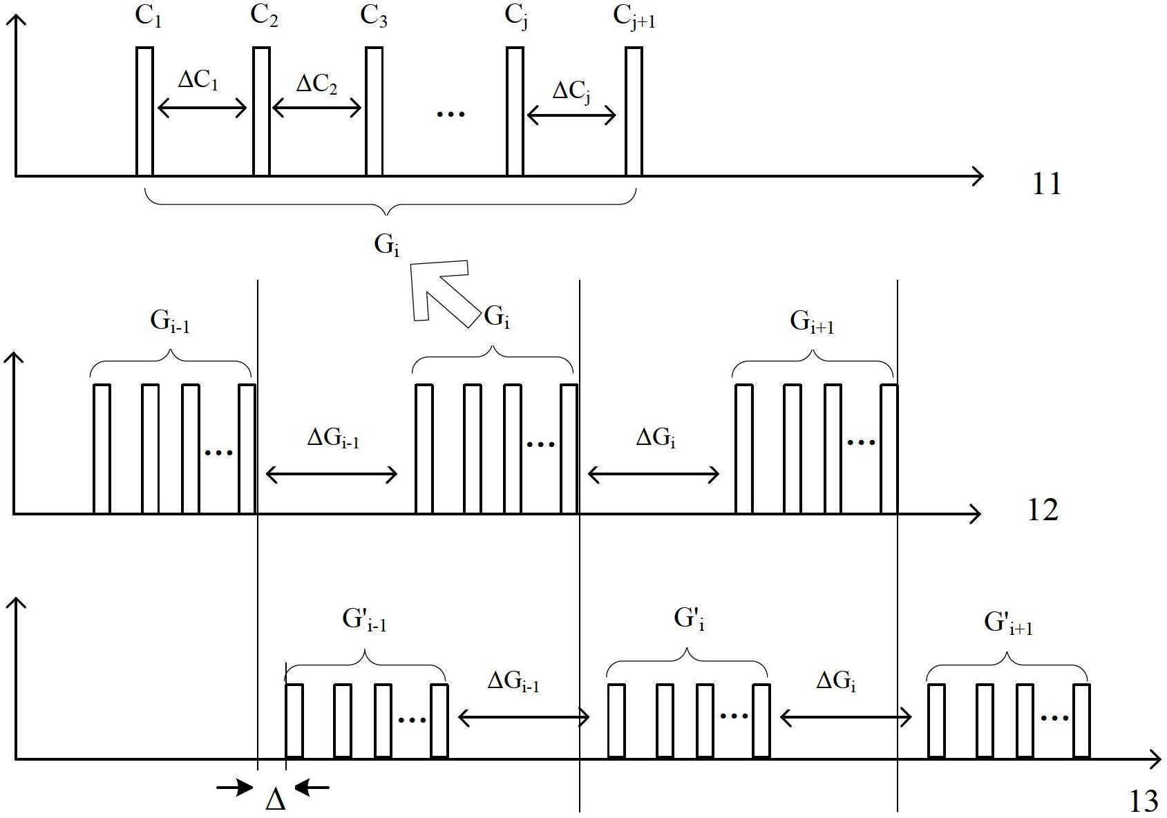
[0037] Refer below figure 1 , figure 2 and image 3 Describe the laser detection method based on dense pulses of the present invention. The detection laser pulses emitted by the laser to the target are not continuously emitted, but are emitted in groups. The time interval between the detection laser pulses can be equal or unequal, and the measured target can be a cooperative target It can also be a non-cooperative target, and the distance of the measured target relative to the laser and the first photoelectric receiver can be unknown, which is suitable for the detection of fast moving targets and is not affected by atmospheric turbulence.

[0038] figure 1 It is a flo...


PUM


Abstract

The invention relates to the field of laser detection, and discloses a laser detection method based on dense pulses. The laser detection method includes steps that a laser emits grouping detection laser pulses to detected targets, wherein the number of the grouping detection laser pulses is larger than or equal to one, and each group of detection laser pulses includes multiple dense pulses; a first photoelectric converter receives echo laser pulses of the detection laser pulses reflected by the detected targets and surrounding environment optical noises, converts the echo laser pulses and the optical noises into corresponding electric signals, wherein the echo laser pulses include information of the detected targets; a signal processor is used for processing the electric signals converted by a detection unit, highlighting the electric signals corresponding to the echo laser pulses according to the time interval among the dense pulses, suppressing electric noises generated by the electric signals corresponding to the optical noises and circuits, and finally acquiring information of the detected target according to the electric signals corresponding to the echo laser pulses. The laser detection method based on the dense pulses can suppress noises, highlight signals, increase signal to noise ratio and reduce the minimum detectable optical power.

Description

technical field [0001] The invention relates to the technical field of laser detection, in particular to a dense pulse-based laser detection method. Background technique [0002] The development of weak light detection devices and their corresponding weak signal processing circuits has made the light power that people can detect smaller and smaller. Certain specifications of photomultiplier tubes and avalanche photodiodes (APD) can respond to a single photon, so the application For single photon detection (Wolfgang Becker.Advanced time-correlated single photon counting techniques[M].2005, Berlin, Heidelberg: Springer Verlag Berlin Heidelberg), for 500nm visible light, the corresponding single photon energy is 4×10 -19 J, it can be seen that the detectable light energy is very small, so it can be used for extremely weak light detection. In practical applications, when performing light detection, in many cases, in addition to the signal light entering the photodetector, stray...

Claims


Application Information

Patent Timeline
IPC IPC(8): G01S7/483G01S17/08
Inventor 巩马理王涛王巍柳强闫平黄磊张海涛刘欢
Owner TSINGHUA UNIV
Learn More