Balance microstrip line feed ultra-wideband dipole antenna

A technology for balancing microstrip lines and dipole antennas, applied in the direction of antenna grounding switch structure connection, radiation element structure, etc., can solve the problems of poor omnidirectional pattern symmetry, poor feed balance, and low broadband index, etc., to achieve The effect of compact structure, small size and high bandwidth

Active Publication Date: 2014-02-12
HARBIN INST OF TECH
View PDF6 Cites 0 Cited by
  • Summary
  • Abstract
  • Description
  • Claims
  • Application Information

AI Technical Summary

Problems solved by technology

[0006] In order to solve the problems of low broadband index, poor feeding balance, poor omnidirectional pattern symmetry and large antenna size in the existing ultra-wideband antenna, the present invention further provides an ultra-wideband dual antenna with balanced microstrip line feeding polar antenna

Method used


Image

  • Balance microstrip line feed ultra-wideband dipole antenna
  • Balance microstrip line feed ultra-wideband dipole antenna
  • Balance microstrip line feed ultra-wideband dipole antenna

Examples


specific Embodiment approach 1

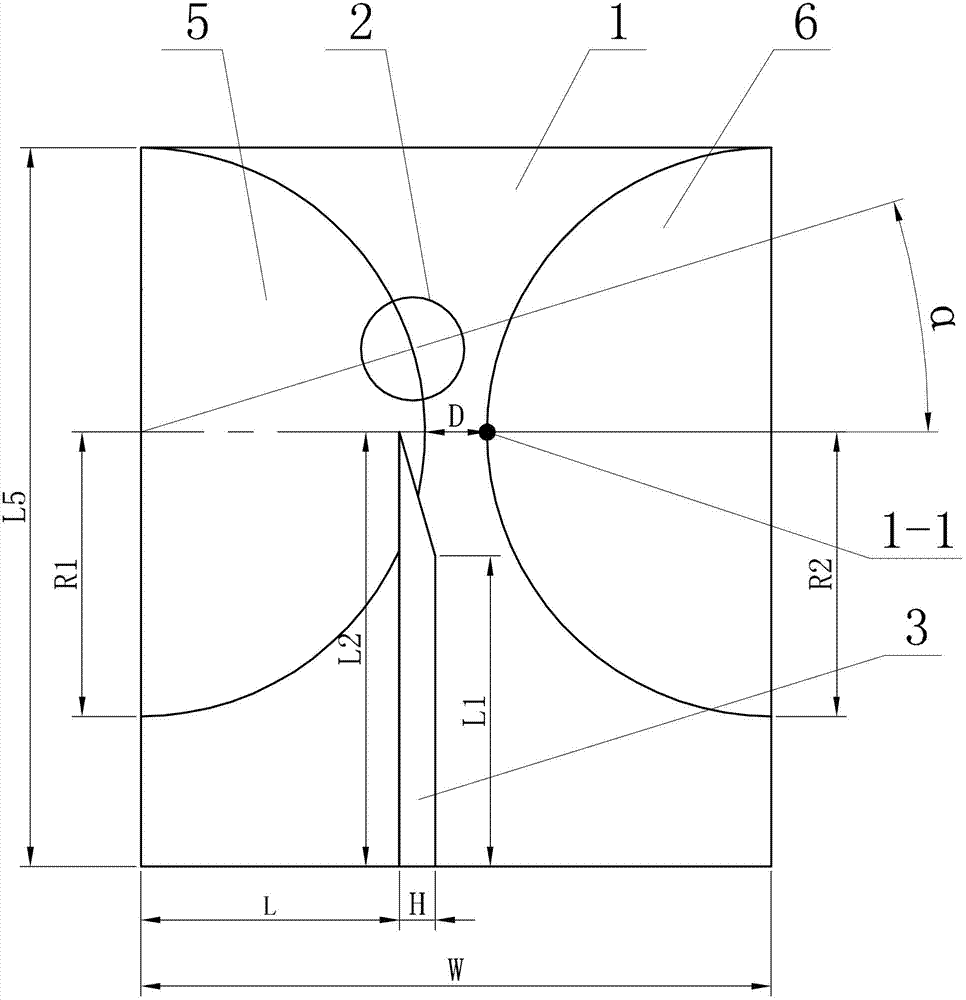
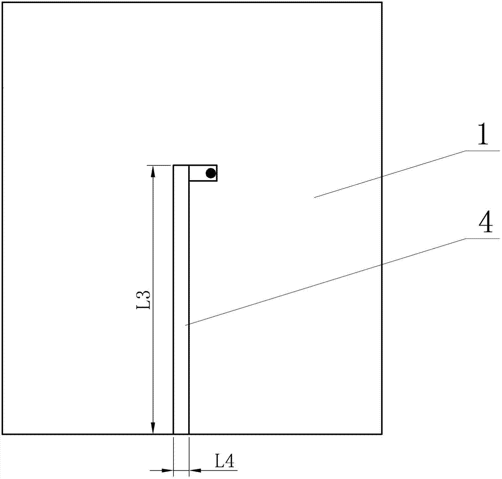
[0013] Specific implementation mode one: combine Figure 1~2 Explain that the ultra-wideband dipole antenna fed by a balanced microstrip line in this embodiment includes a dielectric plate 1, a loaded metal disc 2, a patch 3 on the balanced microstrip line, a patch 4 under the balanced microstrip line, and a first half The circular vibrator 5 and the second semicircular vibrator 6, the first semicircular vibrator 5 and the second semicircular vibrator 6 are horizontally arranged on the upper end surface of the dielectric plate 1, the first semicircular vibrator 5 The straight side and the straight side of the second semicircle vibrator 6 are symmetrically arranged on the left and right ends of the dielectric plate 1, the radii of the first semicircle vibrator 5 and the second semicircle vibrator 6 are set equal, and the first semicircle The difference D between the center distance of the shaped vibrator 5 and the second semicircular vibrator 6 and the diameter of the first sem...

specific Embodiment approach 2

[0017] Embodiment 2: The relative dielectric constant of the dielectric plate 1 in this embodiment is 4.4, and the thickness is 1.5 mm. With such a design, the profile of the antenna is low, and the widely used FR4 epoxy board can be used to manufacture, which can significantly reduce the cost. Other compositions and connections are the same as those in Embodiment 1.

specific Embodiment approach 3

[0018] Specific implementation mode three: combination figure 1 Note that, in this embodiment, both the radius R1 of the first semicircular vibrator 5 and the radius R2 of the second semicircular vibrator 6 are 11 mm. Such a design can ensure that the initial operating frequency of the antenna is low while having an extremely wide frequency band. Other compositions and connections are the same as those in the first or second embodiment.


PUM


Abstract

The invention discloses a balance microstrip line feed ultra-wideband dipole antenna which relates to the field of ultra-wideband dipole antennas, and aims to solve the problems of low wideband indicator, poor feed balance, poor pattern symmetry and quite large size of an antenna of an existing ultra-wideband antenna. A first semi-circular vibrator and a second semi-circular vibrator are horizontally arranged on the upper end surface of a medium plate; the upper patches of a balance microstrip line are horizontally arranged on the upper end surface of the medium plate along a longitudinal direction; one ends of the upper patches of the balance microstrip line are contacted with the first semi-circular vibrator, and the other ends of the upper patches of the balance microstrip line are arranged on the edge of the medium plate; one ends of the lower patches of the balance microstrip line are connected with the second semi-circular vibrator through metallized through holes, and the other ends of the lower patches of the balance microstrip line are arranged on the edge of the medium plate; and the upper patches and the lower patches of the balance microstrip line are arranged correspondingly up and down. The ultra-wideband dipole antenna is adopted as an element for transmitting or receiving electromagnetic wave in an ultra-wideband wireless communication system.

Description

technical field [0001] The invention relates to an ultra-wideband dipole antenna, which belongs to the field of radio technology. Background technique [0002] Antennas are the key components for transmitting and receiving signals in ultra-wideband systems. With the wide application of ultra-wideband technology, the research on ultra-wideband antennas has become increasingly important. The design of ultra-wideband antennas has also attracted more and more attention. New UWB antennas continue to emerge in new forms and new capabilities. Ultra-wideband antennas also drive the development of wideband spectrum analyzers and receivers, enabling broadband antennas to have good receiving and transmitting performance in the entire frequency range of EMC. [0003] UWB is suitable for high-speed, short-distance wireless personal communication, and also suitable for short-distance digital audio and video wireless links, short-distance broadband high-speed wireless access and other rel...

Claims


Application Information

Patent Timeline
Patent Type & Authority Patents(China)
IPC IPC(8): H01Q1/38H01Q1/50
Inventor 田雨林澍陆加宋新吴迪刘家宏刘梦芊
Owner HARBIN INST OF TECH
Why Eureka
Try Eureka