Air-pressure-type retraction self-destruction syringe

A pneumatic and syringe technology, applied in the field of syringes, can solve the problems of complex assembly, poor reliability of special assembly machinery, high cost, etc., and achieve the effects of reducing air compression, easy processing and molding, and reliable air sealing

Inactive Publication Date: 2012-10-03
蔡根顺
View PDF6 Cites 11 Cited by
  • Summary
  • Abstract
  • Description
  • Claims
  • Application Information

AI Technical Summary

Problems solved by technology

[0004] This technology has the following disadvantages: ①There are many accessories, and the structure of the vacuum push rod and the injection rod is relatively complicated, and the cost is high; Push the tail of the rod to the front end of the injection rod, then put the vacuum push rod into the injection rod, and push the vacuum push rod from the tail of the injection rod to the front end of the injection rod according to the set method, and then pull the vacuum push rod back After reaching a certain distance, turn the vacuum push rod so that the lower end of the vacuum push rod is clamped with the limit structure, and because of its complicated assembly process, the reliability of the special assembly machine designed is poor, and it is difficult to produce on a large scale. Manual assembly, all assembly processes need to be carried out manually, which puts a large burden on the staff; ③The technology itself is complicated, difficult to implement, high cost, poor market acceptance, difficult to promote, and low practicability

Method used


Image

  • Air-pressure-type retraction self-destruction syringe
  • Air-pressure-type retraction self-destruction syringe
  • Air-pressure-type retraction self-destruction syringe

Examples


Embodiment Construction

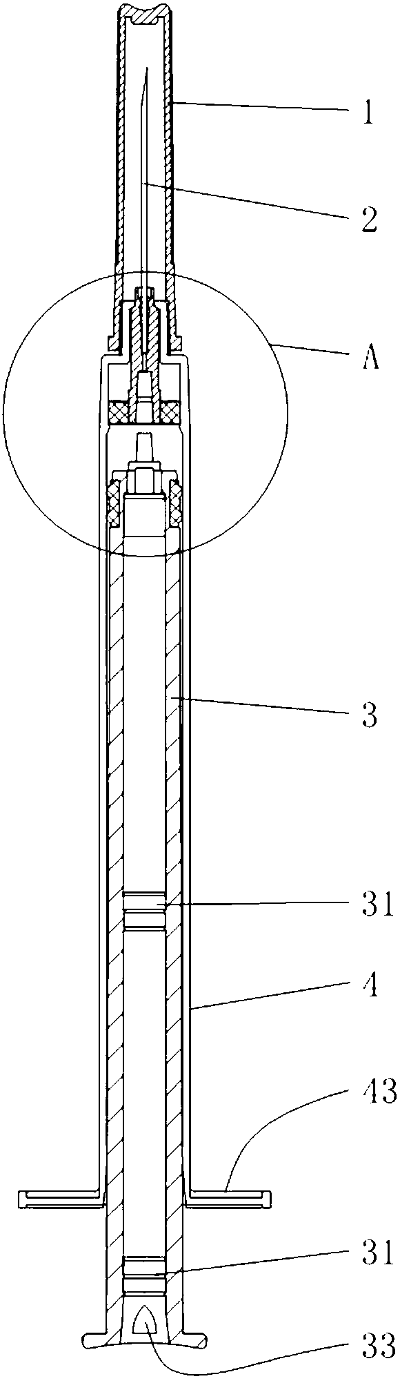
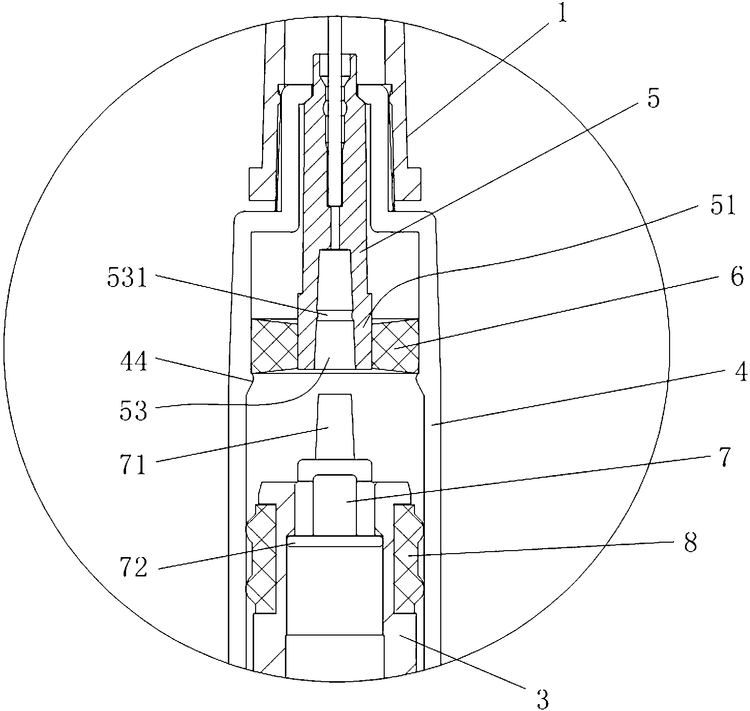
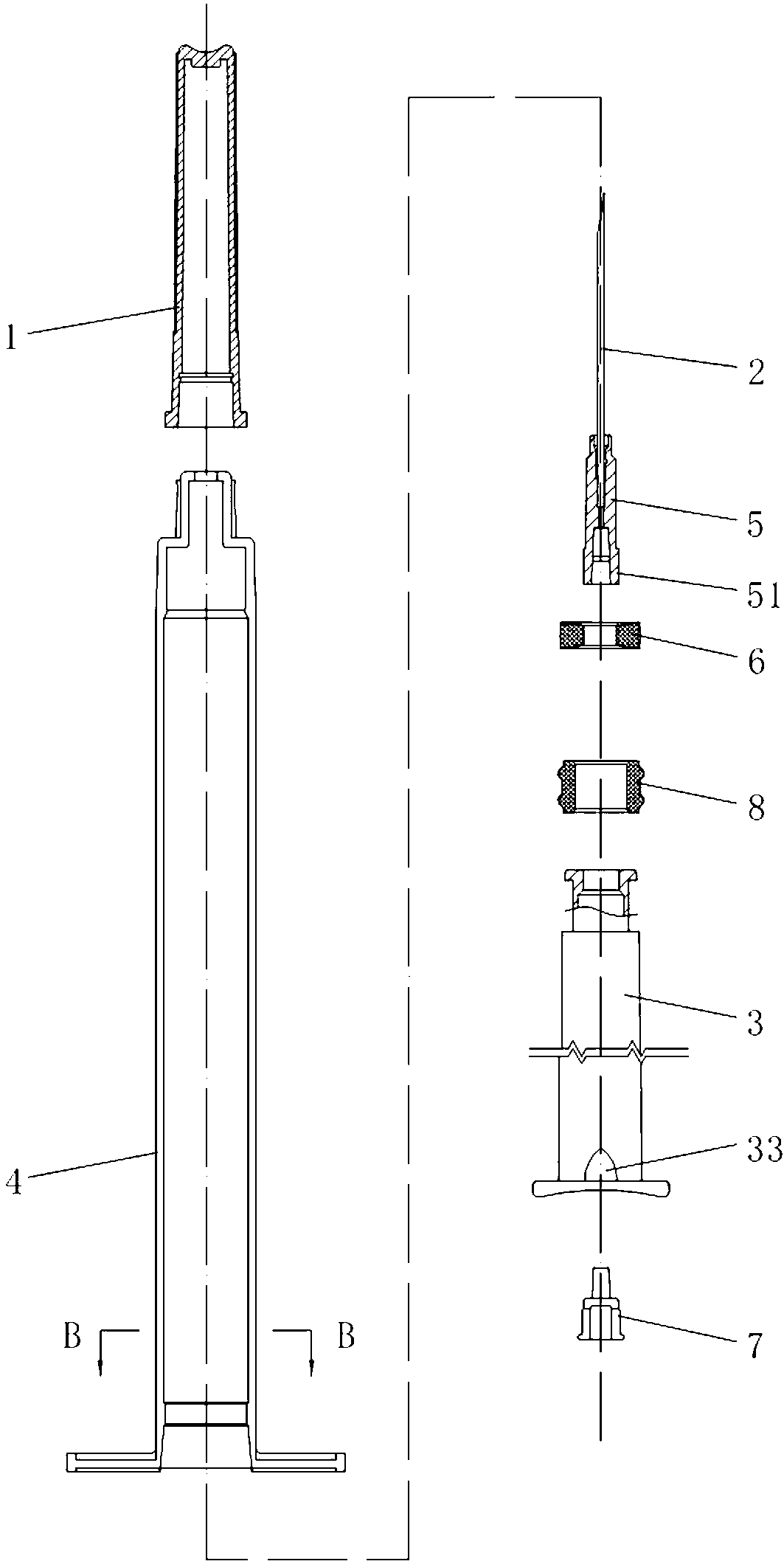
[0023] Such as figure 1 Shown in -6, a kind of air pressure retractable self-destructing syringe comprises injection barrel 4, cylindrical hollow injection rod 3, needle seat 5, sealing ring 6, piston 8 and sealing joint 7, and the center of needle seat 5 is provided with The needle 2 and the needle base 5 are mounted on the front end of the injection barrel 4 through the sealing ring 6 set on the lower end, the piston 8 is set on the outside of the front end of the injection rod 3, the sealing joint 7 is arranged on the inside of the front end of the injection rod 3, and the sealing joint 7 and the needle seat 5 are provided with a coupling structure that cooperates with each other. When the injection rod 3 is pushed to the front end of the syringe 4, the inner wall of the front end of the syringe 4 and the outer wall of the front end of the needle seat 5 are airtight, and the inner wall of the injection rod 3 There is a limit device 31 on the top that prevents the sealing jo...


PUM


Abstract

The invention belongs to the technical field of syringes, and in particular relates to an air-pressure-type retraction self-destruction syringe. The air-pressure-type retraction self-destruction syringe comprises a syringe, a hollow injection rod, a needle seat, a seal ring, a piston and a seal joint, wherein connection structures which are matched with each other are respectively formed on the seal joint and the needle seat, the inner wall of the front end of the syringe is hermetically sealed with the outer wall of the front end of the needle seat, a limit device is arranged on the inner wall of the injection rod, and the lower end of the injection rod is provided with a vent hole. The air-pressure-type retraction self-destruction syringe has a simple structure and is easy to process and form, low in manufacture cost and simple to assemble, and the labor intensity of an operator is small. The self-destruction of the air-pressure-type retraction self-destruction syringe is completed through two steps, wherein the seal joint is inserted into the needle seat through the force of the fingers of the operator and loosens while the injection is injected, the seal ring is continuously pushed forwards to generate air pressure, and energy released from compressing of air is utilized to inject the seal joint into the injection rod, so that the precision requirement on the self-destruction syringe is lowered, the air compression degree required by the self-destruction is reduced, and thus the self-destruction is easier and reliable.

Description

technical field [0001] The invention belongs to the technical field of syringes, in particular to a pneumatic retractable self-destructing syringe. Background technique [0002] Patent No. ZL 200920113284.X discloses a self-destructing vacuum safety syringe, which includes an injection barrel and an injection rod. A piston is arranged at the front end of the injection rod, and a needle seat with a needle head is fixed at the front end of the injection barrel. The needle seat It has a liquid hole that can connect the needle and the injection barrel. The injection rod is a cylindrical hollow rod. A vacuum push rod is inserted into the injection rod. A sealing joint is installed at the front end of the injection rod. The injection rod is connected between the sealing joint and the vacuum push rod A vacuum cavity is formed between the sealing joint and the needle seat. When the injection rod is pushed to the front end of the injection cylinder, there is a connecting structure t...

Claims


Application Information

Patent Timeline
Patent Type & Authority Applications(China)
IPC IPC(8): A61M5/50A61M5/178
CPCA61M5/315A61M5/178A61M5/50A61M5/322A61M5/3234A61M5/508A61M2005/323A61M2005/3242A61M5/3221A61M2005/3231
Inventor 蔡根顺
Owner 蔡根顺
Why Eureka
Try Eureka