Eureka AIR delivers breakthrough ideas for toughest innovation challenges, trusted by R&D personnel around the world.

Whirlwind thread tapping machine

A screw machine and cyclone technology, applied in the field of mechanical processing, can solve the problems of troublesome workpiece clamping, inability to be widely used, low efficiency of workpiece loading and unloading, etc., and achieve the effect of good processing quality, compact structure and simple structure

Inactive Publication Date: 2012-10-03
吕杭云
View PDF6 Cites 6 Cited by
  • Summary
  • Abstract
  • Description
  • Claims
  • Application Information

AI Technical Summary

Problems solved by technology

[0004] However, because the current whirlwind cutting thread needs to be used in conjunction with a lathe, the workpiece needs to be clamped on the lathe, and the lathe controls the rotation and feed movement of the workpiece, so the processed workpiece is limited and can only process cylinders or cylinders. The workpiece, such as a screw, and the workpiece clamping on the lathe are troublesome; because the workpiece rotates on the machine tool, it is necessary to wait for the workpiece to stop rotating before unloading the workpiece, resulting in low loading and unloading efficiency of the workpiece; because it is used as a set, if the workpiece requires multiple processing , such as processing both ends of the workpiece, then it needs to go through two loading and unloading and two feed processing
[0005] Therefore, the current whirlwind cutting thread has some shortcomings, and the processing range is very limited, so it cannot be widely used.

Method used


Image

  • Whirlwind thread tapping machine
  • Whirlwind thread tapping machine
  • Whirlwind thread tapping machine

Examples


Embodiment Construction

[0018] The present invention will be further explained below in conjunction with the drawings:

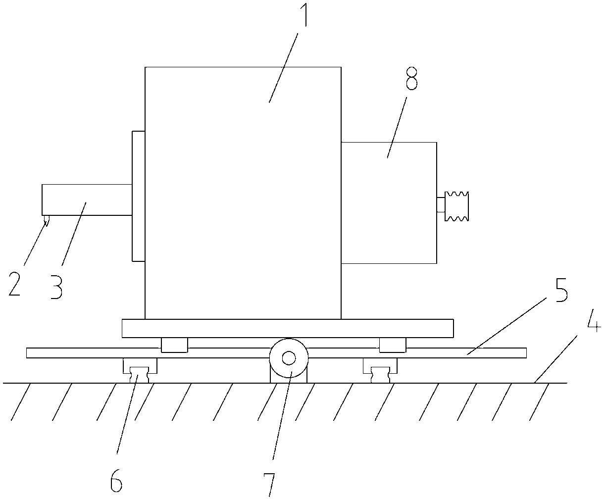
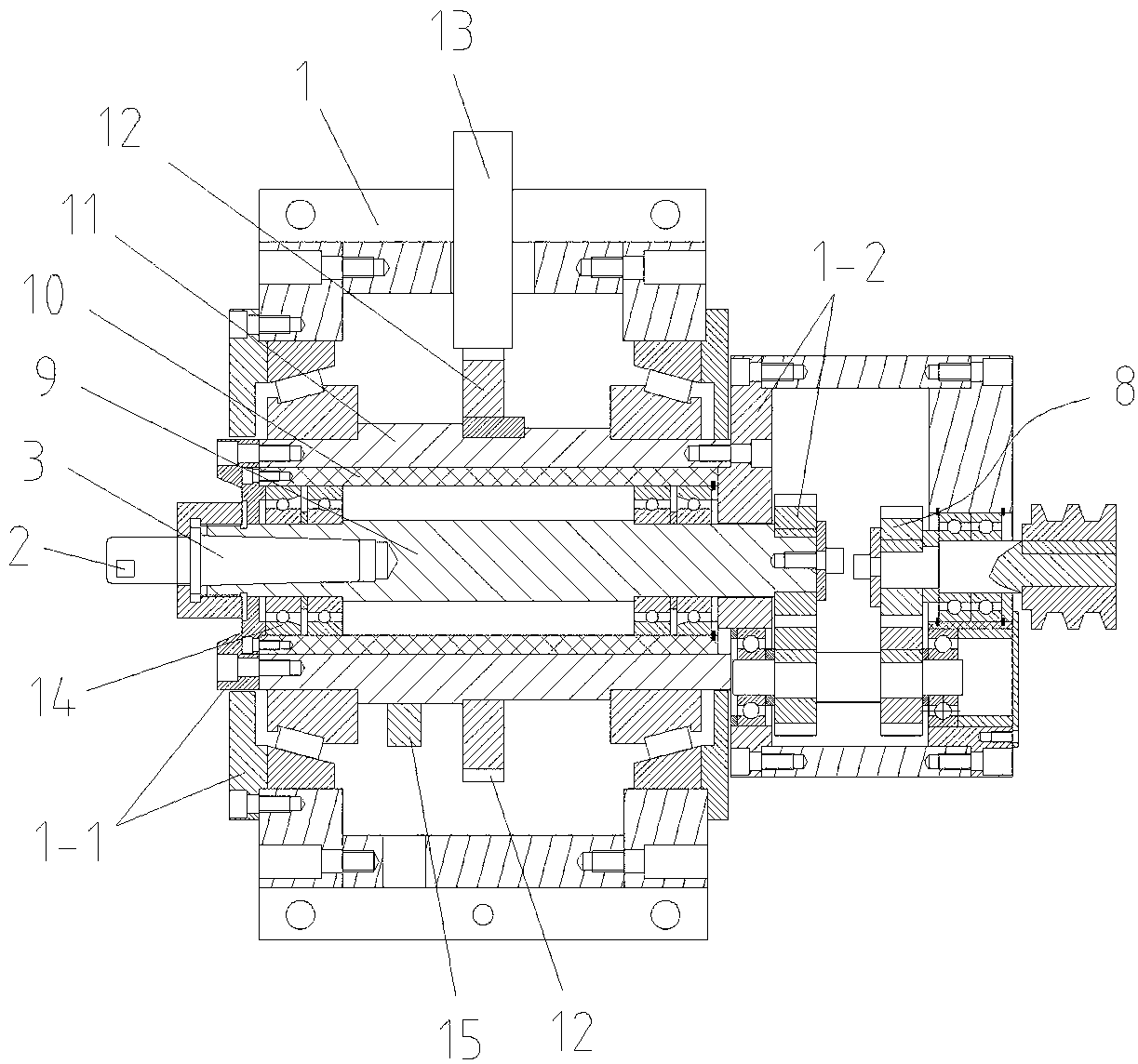
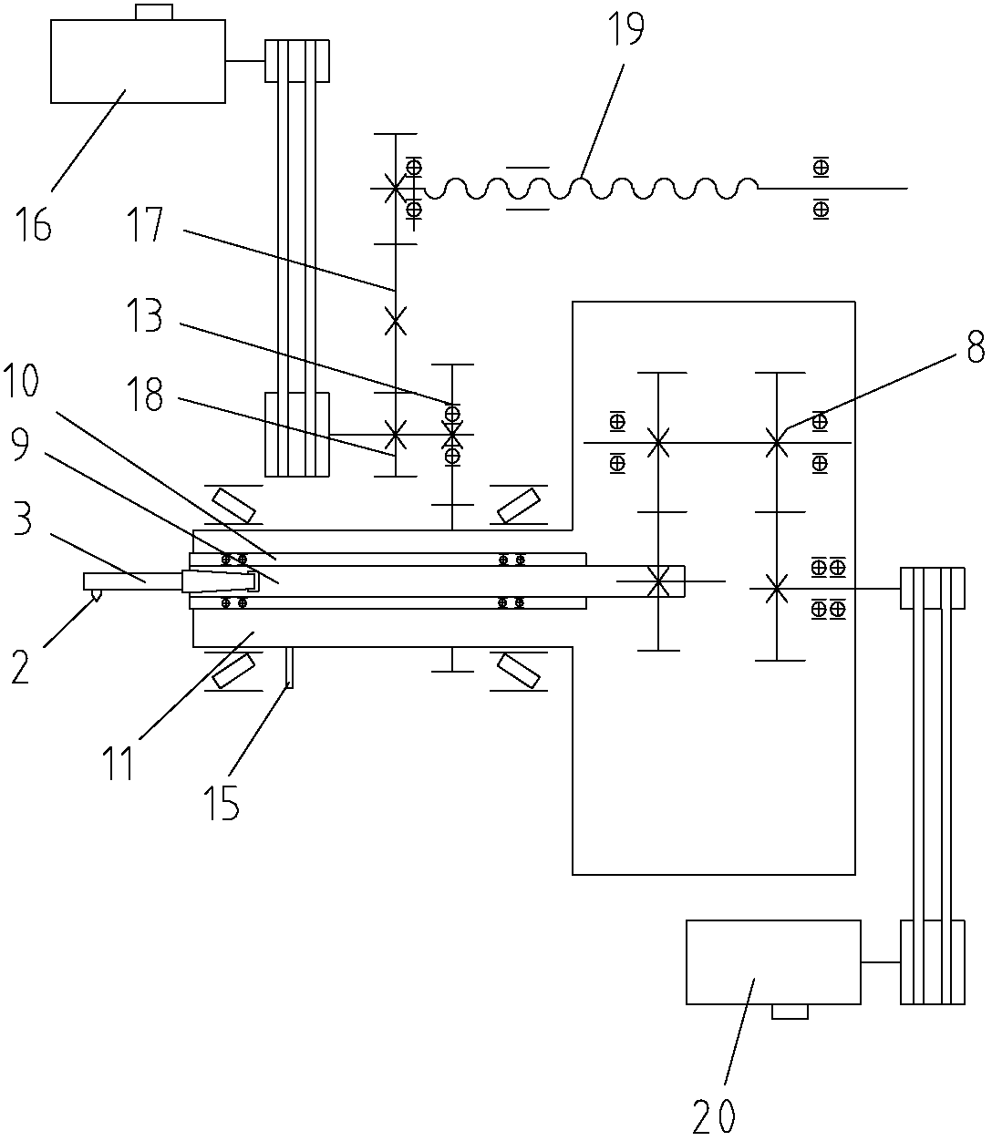
[0019] Refer to the attached drawings: this whirlwind thread cutting machine includes a worktable 4, a machine body 1 is provided on the worktable 4, a cutter bar 3 is provided on the machine body 1, and a milling cutter 2 is fixed on the end of the cutter bar 3, of which the cutter bar 3 Fixed on the axis of the autorotating main shaft 9, wherein the body 1 is provided with an eccentric shaft barrel 11 for installing the autorotating main shaft 9, wherein the autorotating main shaft 9 is installed at an eccentric position in the eccentric shaft barrel 11, and the rear end of the autorotating main shaft 9 passes through The eccentric shaft barrel 11 is connected with a rotation motor 20 through a gear box 8; wherein the eccentric shaft barrel 11 is connected with a revolution motor 16 that drives it to rotate; wherein a horizontal guide rail 5 is provided on the workbench 4, and a cont...


PUM


Abstract

The invention provides a whirlwind thread tapping machine, comprising an operating platform. A machine body is arranged on the operating platform; a tool rod is arranged on the machine body; a milling tool is fixedly arranged on the end head of the tool rod; the tool rod is fixedly arranged an axis of a rotation main shaft; an eccentric shaft cylinder provided with the rotation main shaft is arranged in the machine body; the rotation main shaft is mounted at an eccentric position inside the eccentric shaft cylinder; the rear end of the rotation main shaft passes through the eccentric shaft cylinder and is connected with a rotation motor through a gear box; the eccentric shaft cylinder is connected with a revolution motor for driving the eccentric shaft cylinder to rotate; a transverse guide rail is arranged on the operating platform; the machine body is arranged on the guide rail; a screw rod for controlling the machine body to transversely slide is arranged on the operating platform; the screw rod is connected on the revolution motor; and the rotation main shaft and the eccentric shaft cylinder are mounted on the machine body through a front end cover and a rear end core. The improved structure of the whirlwind thread tapping machine not only has a relatively wide application range, but also can be used for machining a plurality of positions and end surfaces of one work piece by using a plurality of devices as the work piece is fixed, so that the relatively high efficiency and the relatively strong function can be achieved.

Description

Technical field [0001] The invention relates to the field of machining, in particular to a whirlwind thread cutting machine for cutting internal and external threads. Background technique [0002] Cyclone thread cutting is a more advanced and efficient method of threading. It is suitable for the production of parts with large batches and high precision requirements. It can be cut at one time during the processing process, and the surface quality of the cut is good, and the processed The failure rate of the product is small, so the whirlwind cutting thread has higher efficiency and quality than the current ordinary tapping method. [0003] Cyclone cutting threads need to complete five machining motions during the machining process: the cutter head drives the cemented carbide forming tool to rotate at high speed (main motion); the machine tool spindle drives the workpiece to rotate slowly (auxiliary motion); whirlwind milling is based on the workpiece pitch or lead edge Workpiece a...

Claims


Application Information

Patent Timeline
Patent Type & Authority Applications(China)
IPC IPC(8): B23G1/32B23G1/44
Inventor 吕杭云郑卫锋
Owner 吕杭云
Why Eureka
Eureka Blog
Learn More