
Linear evaporation source device and precise evaporation rate control evaporating unit with same

A linear evaporation source and evaporation rate technology, applied in vacuum evaporation plating, ion implantation plating, metal material coating process, etc., can solve the problems affecting the quality and life of the device, affecting the uniformity of the coating layer of the glass substrate, etc. To achieve the effect of controlling the uniformity of coating and the concentration of evaporated substances

Inactive Publication Date: 2012-10-03
DONGGUAN ANWELL DIGITAL MASCH CO LTD
View PDF3 Cites 13 Cited by
  • Summary
  • Abstract
  • Description
  • Claims
  • Application Information

AI Technical Summary

Problems solved by technology

Since the concentration of the evaporating substance is arranged in a decreasing manner from the center of the evaporation source nozzle to both sides, the thickness of the coating layer at the part of the glass substrate facing the evaporation source nozzle is correspondingly thicker than that of other parts of the glass substrate , thus seriously affecting the uniformity of the coating layer of the glass substrate, and correspondingly affecting the quality and life of subsequent devices

Method used


Image

  • Linear evaporation source device and precise evaporation rate control evaporating unit with same
  • Linear evaporation source device and precise evaporation rate control evaporating unit with same
  • Linear evaporation source device and precise evaporation rate control evaporating unit with same

Examples


Embodiment Construction

[0028] In order to describe the technical content and structural features of the present invention in detail, further descriptions will be made below in conjunction with the embodiments and accompanying drawings.

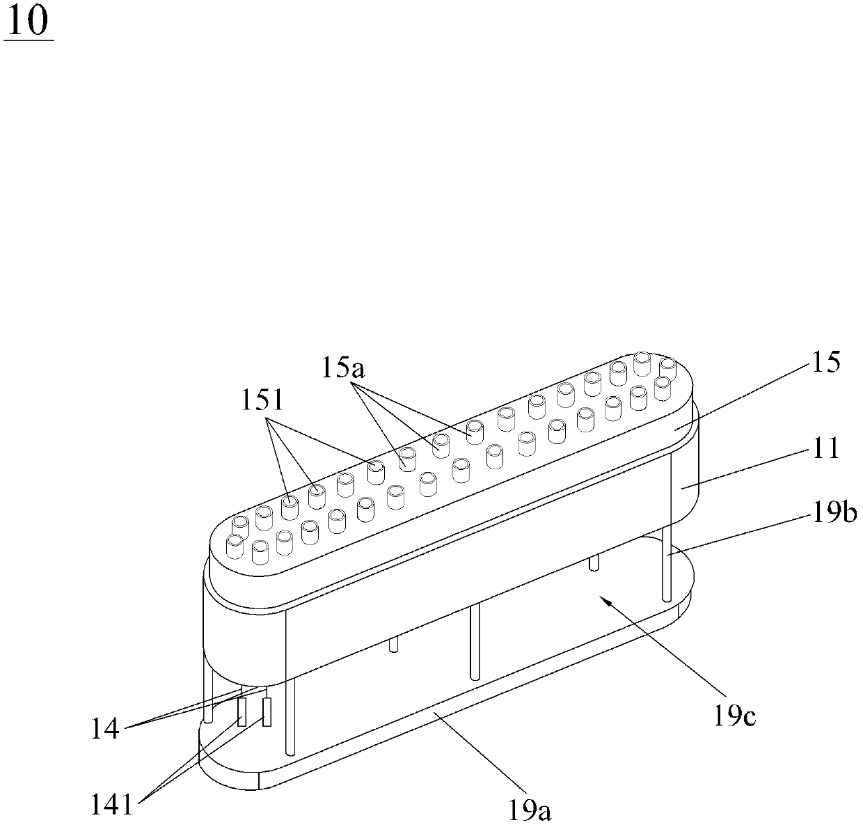
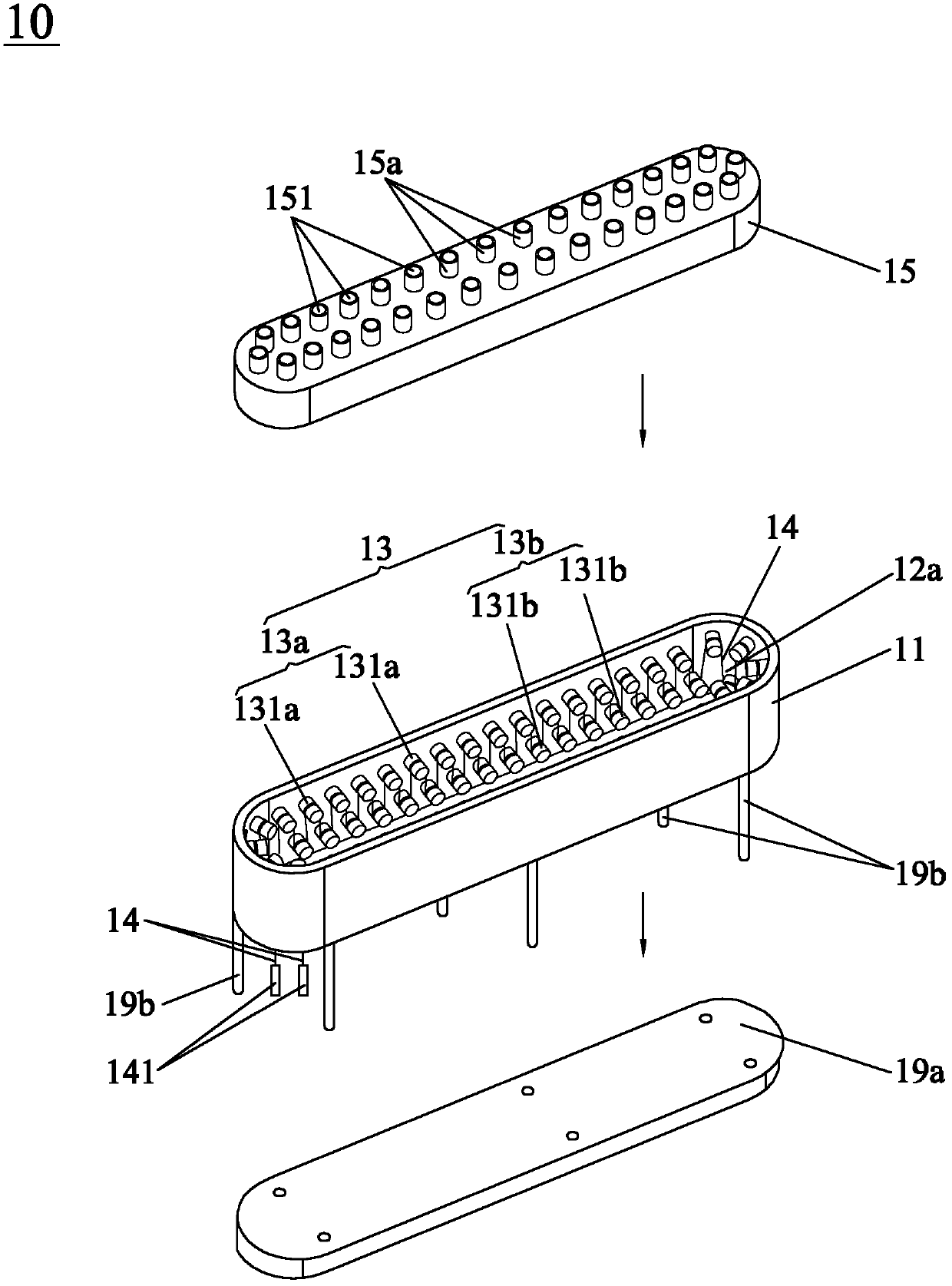
[0029] see figure 1 and figure 2 , the linear evaporation source device 10 of the present invention is used to be arranged in the vacuum chamber 21 of the vacuum chamber body 20 that is a vacuum environment (see Figure 10) to perform linear evaporation on the evaporation source, wherein the linear evaporation source device 10 includes a device body 11 , an insulating sheath assembly 13 , a heating wire 14 and an evaporation cover 15 . The device body 11 is provided with a receiving groove 12a with an upward opening; in this embodiment, the insulating sleeve assembly 13 is fixed in the receiving groove 12a and includes a first horizontal insulating sleeve row 13a and a second horizontal insulating sleeve row 13b, the first horizontal insulating sleeve row 13a inc...


PUM


Abstract

The invention provides a linear evaporation source device for evaporating an evaporation source in a vacuum. The linear evaporation source device comprises a body, an insulating sleeve component, a heating wire and an evaporating cover. The body is provided with a containing trough with an upward opening. The insulating sleeve component is fixed inside the containing trough and comprises a first horizontal insulating sleeve row. The first horizontal insulating sleeve row comprises a plurality of first insulating sleeves projecting at intervals inside the containing trough at the same height. The heating wire is sequentially wound on the first insulating sleeves, and both ends of the heating wire are connected with an external power source electrically. The evaporating cover covers the body and forms a heating cavity with the containing trough. The evaporating cover is provided with holding sockets in one-to-one correspondence to the first insulating sleeves. The holding sockets penetrate through the evaporating cover to form evaporating holes. The linear evaporation source device is capable of forming a plurality of independent evaporation point sources, concentration of evaporated material is evener at any position, and accordingly excellent conditions are created for even coating of a substrate. In addition, the invention further discloses a precise evaporation rate control evaporating unit.

Description

technical field [0001] The present invention relates to an evaporation source device and evaporation equipment with the evaporation source device, in particular to a linear evaporation source device which is suitable for being arranged in a vacuum chamber in a vacuum environment to perform linear evaporation on the evaporation source and has the linear evaporation source The evaporation rate of the device is precisely controlled evaporation equipment. Background technique [0002] Thin sheets such as glass substrates have been widely used in the manufacture of LCD-TFT displays, organic light-emitting display device (OLED) panels, solar panels, and the like. In such applications, thin films are mostly deposited on clean glass. The process for such large glass substrates usually involves the implementation of multiple sequential steps, including chemical vapor deposition (CVD), physical vapor deposition (PVD), organic substances Evaporation, magnetron sputtering deposition or...

Claims


Application Information

Patent Timeline
Patent Type & Authority Applications(China)
IPC IPC(8): C23C14/26
Inventor 王曼媛范继良刘惠森
Owner DONGGUAN ANWELL DIGITAL MASCH CO LTD
Learn More